ZR36015 Просмотр технического описания (PDF) - Unspecified
Номер в каталоге
Компоненты Описание
Список матч
ZR36015 Datasheet PDF : 27 Pages
| |||
PRELIMINARY
ZR36015
HEN
A
B
A > 48 SYSCLK Cycles
B is an even number of SYSCLK cycles
HEN signal must conform to eather a or B
Figure 8. Setting of HEN Timing
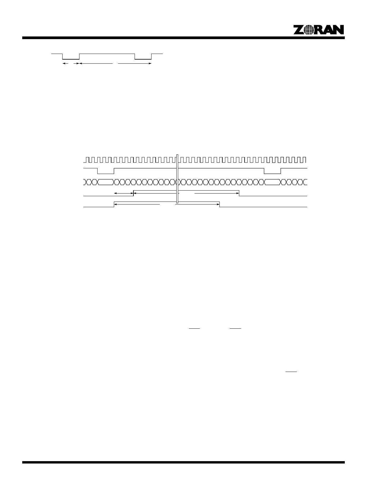
Window Output Signal
The WINDOW output (active high) is aligned with the PDATA bus, identifying the pixels which correspond to the active image area.
Figure 5 shows the functional timing for the window signal for the case where Mode=0, and HDelay = 0 or HDelay = 3.
The Window signal is set “HDelay” pixels after the rise of HEN, and goes inactive “HWidth” pixels later. The timing for the WINDOW
signal is identical for both compression and expansion modes.
SYSCLK
HEN
PXDATA
ex. MOD = 0
WINDOW
ex. HDelay = 3
WINDOW
ex. HDelay = 0
012345
HDelay
HWidth
HWidth
N = HDelay+HWidth
N
Figure 9. Example of Window Output Timing
Line Counting
The ZR36015 counts the number of lines that were processed during encoding mode, and stores this number in the “number of lines”
registers defined in Table 5.
When “VHeight” is set to zero, the number of lines processed is dependent on the duration of the VEN signal. If the duration of the
VEN signal does not correspond to an active image area with a number of lines that is a multiple of 8 (for modes 0,1,3) or a multiple
of 16 (mode 2) then the number of lines is rounded up to the nearest multiple of 8(16). This feature ensures blocks of data that are
compatible with JPEG image compression algorithms.
If the number of lines being processed exceeds 8192, then the ZR36015 terminates the processing after processing 8192 lines.
“BUSY” Bit and Busy Signal Timing
The BSY (Busy) bit in the Mode Register is set to ‘1’ (active) when the Go bit is aserted. When the ZR365015 finishes processing the
data in the active image area, it clears the BSY and GO bits and the BSY signal. The BSY signal follows the BSY bit when VEN falls.
Setting GO
The GO bit in the Mode Register is set in order to begin processing of an image. Before setting the GO bit, the ZR36015‘s Mode
Register and Table values should be configured for the desired operation, and the BSY bit (in the Mode Register) should be checked
to insure that it is not set. If the BSY bit is set, this indicates that the previous process has not completed, and so the ZR36015 is not
ready to start a new process. If the BSY bit is not set, then the ZR36015 is free to begin a new process. The BSYsignal can be mon-
itored to determine when the previous process is complete.
When the GO bit is set, then the ZR36015 will respond to the next VEN that is sees. The GO bit must be set at lease 3 SYSCLK
cycles before the trailing edge of VEN in order to respond to the next active high pulse of VEN. If the GO bit is not set at least 3
8
Share Link: 