ZR36015 Просмотр технического описания (PDF) - Unspecified
Номер в каталоге
Компоненты Описание
Список матч
ZR36015 Datasheet PDF : 27 Pages
| |||
PRELIMINARY
ZR36015
The Coder Data Sub-Buffer performs the conversion of the data between the Strip Memories and the Coder Data Bus.
During Compression, pixel data is transferred from the PXDATA Bus to the Strip Memories, and data from the Strip Memories is trans-
ferred to the Coder Data Bus. During Expansion, Coder data is transferred to the Strip Memories, and data from the Strip Memories
is transferred to the Pixel Data Bus.
Figure TBDX7 shows the timing for the data and the control signals for the Strip Buffer Interface.
Note that reads and writes to the Strip Memory are asynchronous to one another, in that either can continue to occur (on alternate
SYSCLK cycles) independently of whether or not the other side is ready to transfer data. The only restriction is that a strip buffer must
be emptied (filled) before its time to switch sides (or else the CBSY signal becomes active (see section TBD)
Strip Buffer
In Compression, the raster format data is read into the Strip Buffer and stored in interlaced JPEG Block format in the Strip Buffer. This
data is then read out to the Coder Data Bus in interlaced Block format for compression by the JPEG CODEC (ZR36050). In Expan-
sion, the operation is reversed.
For modes 0,1 and 3,the Strip Buffer is filled with the data from 8 lines. For mode 2, data from 16 lines is stored in a Strip Buffer.
The Strip Buffers are composes of an A and B side. The A side stores the even pixel data and the B side stores the odd pixel data.
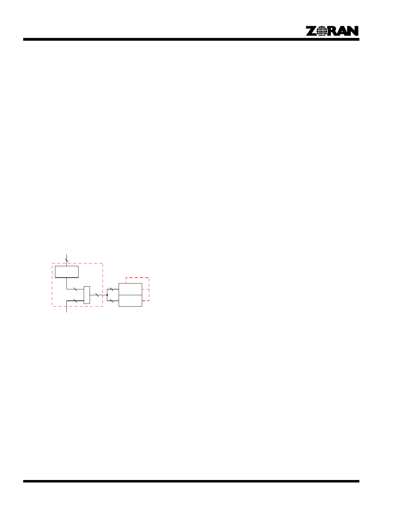
Figure 12 shows the A and B sides to the Strip Buffers.
In order to provide double buffering (two strip buffers), the A and B memories are separated into high and low address spaces. The
high address space of the A and B Memories is indicated by the A’ and B’ shown in the figure below. The starting address of A’ and
B’ is determined by the mode of operation for the ZR36015 and whether decimation is being performed (see the section on Strip buffer
Capacity).
MD0205DN
Pixel
Data Side
16
Strip Memory
ZR36015
Sub Buffer
A’
16
8
A
16
B’
16
8
B
Coder
Data Side
Figure 11. Double-Buffer Configuration
10
Share Link: 