ZR36015 Просмотр технического описания (PDF) - Unspecified
Номер в каталоге
Компоненты Описание
Список матч
ZR36015 Datasheet PDF : 27 Pages
| |||
PRELIMINARY
ZR36015
the status of compression or expansion prcesses. The four
control registers are listed and described below.
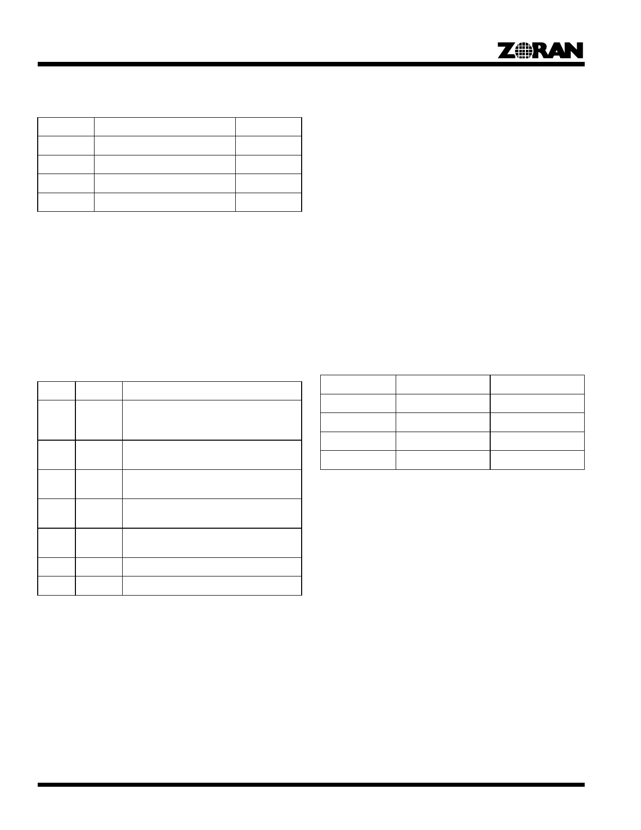
Table 1: Control Register Map
ADD(1:0)
Contents
Host Access
00
Soft Reset
W
01
Mode Register
R/W
10
Address Pointer Register
R/W
11
Configuration Register Tables
R/W
Soft Reset Register (Write Only):
A Write to the Soft Reset Register will abort the current process,
and put the ZR36015 in to the IDLE mode. The Soft Reset does
not modify the internal registers of the ZR36015, except for the
GO bit in the Mode Register (which is cleared).
After a soft reset, the ZR36015 will be in the IDLE state.
To start a new process, the GO bit in the Mode Register must be
set by the Host.
Mode Register (Read/Write):
The table below shows the contents of the Mode Register.
Bit
Name
Description
0
GO Go:
0: ZR36015 IDLE
1: Set to indicate Encode or Decode process.
1
EDC 0: Decode mode selected
1: Encode mode selected
3:2 MOD(1:0) Pixel data Mode Select
(seeTable 2)
4
DCM Decimate data (Compression mode only).
Active High.
5
CSC Select ZR36011 Color Space Converter Mode
(Active High)
6
-
Not Used
7
BSY Busy Flag (Active High)
The definition of these bits is given below:
s BSY: Busy Flag (Read Only)
Active High: Indicates that the ZR36015 is busy performing
an encoding or decoding process. The next process should
not be started until the current process completes (indicated
by the ZR36015 clearing this bit).
The BSY flag is set to ‘1’ immediately after the GO bit is set.
The BSY flag is cleared when the processing for an image is
complete and the ZR36015 is ready for the next “GO”.
Before setting the “GO” bit (defined later in this section), the
host should check that the Busy Flag is ‘0‘, indicating that the
previous process has completed.
s CSC: Select ZR36011 Color Space Converter (Write Only)
Set this bit to a ‘1’ when interfacing the PIXDATA bus to the
ZR36011 Color Space Converter, and to a ‘0’ otherwise.
Setting the CSC bit to a ‘1‘, will modifies the pixel data
internal delays during compression or expansion to match
the delays in the ZR36011 Color Space Converter. A
description of the modified pixel data delays is TBD.
s DCM: Select 1/2 Decimation Write Only)
Set this bit to a ‘1’ when selecting 1/2 decimation mode (for
compression only).
s MOD(1:0): Pixel Data Mode Select
These bits are set to determine the PXDATA bus to/from
BDATA bus mode of operation. Table 3 shows the availiable
combinations.
s EDC: Enclde/Decode select
Selects either encode (EDC = ‘1’), or decode (EDC = ‘0’)
mode.
s GO: Process Go Trigger Bit (Write Only)
Set to ‘1’ to start ZR36015 processing. Prior to setting GO,
the host must...
1) Make sure that the BSY bit is not set.
2) Set all processing parameters in the tables.
When GO is set, the ZR36015 starts counting pixel elements
from the rise of VEN and HEN. When [when is go reset?]
MOD(1:0)
00
01
10
11
PXDATA Format
1:0:0
4:2:2
4:2:2
4:1:1
BDATA Format
1:0:0
4:2:2
4:1:1
4:1:1
Address Pointer Register(R/W):
This register is a pointer to the configuration tables and line
count register. A write to the configuration table (ADD(1:0) =
“0b11”) will write to the table element indicated by the address
pointer regstier. A read from the number of lines registers will
access the register indicated by the address pointer register.
The Address pointer Register is automatically incremented by
one after a read or write with ADD(1:0) set to “0b11”.
Configuration Register Tables(R/W):
The contents of the Configuration Table are shown in the below.
The fields of the Configuration Table are defined below and in
Figure 5.
s HDelay(12:0): Horizontal delay in number of pixel elements
before active window. The setting range for WDelay(12:0) is
0 to 8191.
s HWidth(14:0): Horizontal width of the active image area. The
setting range for Width(14:0) is up to 8191 for.
s VDelay(12:0):Verticle delay in number of pixel elements
before active window. The setting range for HDelay(12:0) is
0 to 8191.
4
Share Link: 