ZR36015 Просмотр технического описания (PDF) - Unspecified
Номер в каталоге
Компоненты Описание
Список матч
ZR36015 Datasheet PDF : 27 Pages
| |||
PRELIMINARY
ZR36015
s VHeight(12:0):Verticle height of the active image area. The
maximum setting for Height(12:0) is 8191. Setting
Height(12:0) to ‘0’ in encode mode, lets the Height of the
active image area be determined by the non-active point of
VEN.
Address Pointer Value
Window Setting Value
0
HDelay(7:0)
1
HDelay(12:8)1
2
HWidth(7:0)
3
HWidth(14:0)1
4
VDelay(7:0)
5
VDelay(12:8)1
6
VWidth(7:0)
7
VWidth(13:8)1
8
Number of Lines(7:0)
9
Number of Lines(13:8)1
1. Assigned to LSB’s of PIXDATA(7:0)
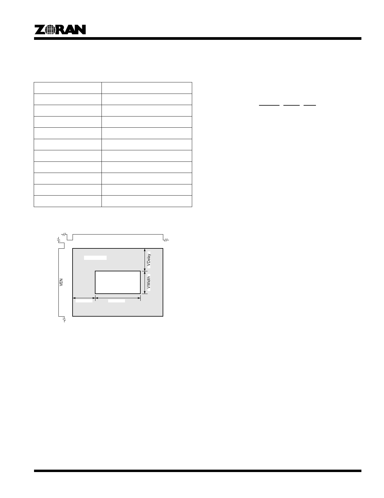
HEN
Enable Area
HDelay
Acitve Image
Area
HWidth
Figure 4. Active Image Area
Number of Lines Table:
The Number of Lines Table holds the number of lines processed
in encoding by the ZR36015.
Operating States
The ZR36015 has four Operating States; Reset, Idle, Compres-
sion and Expansion.
Reset State
While the RESET input is asserted, the ZR36015 is in the Reset
State. In this state the PXDATA and BDATA busses are high
impedance, and the DSYNC, STOP, EOS signals are high
impedance.
After a RESET, the ZR36015 will be in the IDLE state.
Idle State
After a Soft RESET, or after the RESET input signal has been
applied, or at the end of a compression or expansion process,
the ZR36015 will be in the IDLE state. In the IDLE state, no
active processing is taking place, and the PXDATA bus is high
impedance (the bus drivers for the Coder Interface are con-
trolled by the COE signal).
While in the IDLE state, the ZR36015 Configuration Register
Tables can be loaded with the values to select the desired active
image area. Also, the Mode Register is loaded with the desired
Mode of operation, and the number of lines table can be read
To leave the IDLE state and enter one of the processing states
(compression or expansion), the GO bit in the Mode registe is
set.
Compression
When the GO bit is set to “1”, and the EDC bit equals “1”, then
the ZR36015 enters the Compression State.
Setting the GO bit results in the BSY bit in the mode register
being set.
Once the GO bit is set, then on the falling edge of the Verticle
Sync Signal (VEN), the BSY output signal will be set. The BSY
bit (and output signal) will stay set until the end of the Compres-
sion process. The hardware can monitor the BSY signal, to
determine when the Compression process has completed. Note
that the GO bit must be set at least three SYSCLK cycles before
the VEN goes from High to Low (see figure ???).
Following the above, the ZR36015 monitors the VEN input to
detect the transiton of VEN from low to high. This indicates the
beginning of the image to be processed The next VDelay lines
of data are ignored in order to reach the “active image area”.
Then the next VWidth lines of data are processed.
The HEN input synchronizes the line by line transfers of data into
the ZR36015. On the rise of HEN, the next HDelay pixels are
ignored in order to reach the “active image area”. Then the next
HWidth pixels are procesed.
5
Share Link: 