T40HFL_16 Просмотр технического описания (PDF) - Vishay Semiconductors
Номер в каталоге
Компоненты Описание
Список матч
T40HFL_16 Datasheet PDF : 16 Pages
| |||
www.vishay.com
VS-T40HFL, VS-T70HFL, VS-T85HFL Series
Vishay Semiconductors
BLOCKING
PARAMETER
SYMBOL
Maximum peak reverse leakage current IRRM
RMS isolation voltage
VISOL
TEST CONDITIONS
T40HFL T70HFL T85HFL UNITS
TJ = 125 °C
20
mA
50 Hz, circuit to base, all terminals shorted,
TJ = 25 °C, t = 1 s
3500
V
THERMAL AND MECHANICAL SPECIFICATIONS
PARAMETER
SYMBOL
TEST CONDITIONS
VALUES UNITS
Junction operating temperature range
Storage temperature range
Maximum internal thermal
resistance, junction to case
per module
T40HFL
T70HFL
T85HFL
Thermal resistance,
case to heatsink per module
Mounting torque ± 10 %
base to heatsink
busbar to terminal
Approximate weight
Case style
TJ
TStg
RthJC
RthCS
DC operation
Non-lubricated
threads
Mounting surface, flat,
smooth and greased
M3.5 mounting screws (1)
M5 screws terminals
See dimensions -
link at the end of datasheet
-40 to +125
°C
-40 to +150
0.85
0.53
K/W
0.46
0.2
1.3 ± 10 %
Nm
3 ± 10 %
54
g
19
oz.
D-55 (T-module)
Note
(1) A mounting compound is recommended and the torque should be rechecked after a period of about 3 hours to allow for the spread of
the compound
R CONDUCTION
DEVICES
SINUSOIDAL CONDUCTION AT TJ MAXIMUM RECTANGULAR CONDUCTION AT TJ MAXIMUM
180°
120°
90°
60°
30°
180°
120°
90°
60°
30°
T40HFL
T70HFL
0.06
0.08
0.10
0.14
0.24
0.05
0.08
0.10
0.15
0.24
0.05
0.06
0.08
0.11
0.19
0.04
0.06
0.08
0.12
0.19
T85HFL
0.04
0.05
0.06
0.09
0.15
0.03
0.05
0.07
0.09
0.015
Note
• The table above shows the increment of thermal resistance RthJC when devices operate at different conduction angles than DC
UNITS
K/W
130
120
110
100
90
80
70
60
50
0
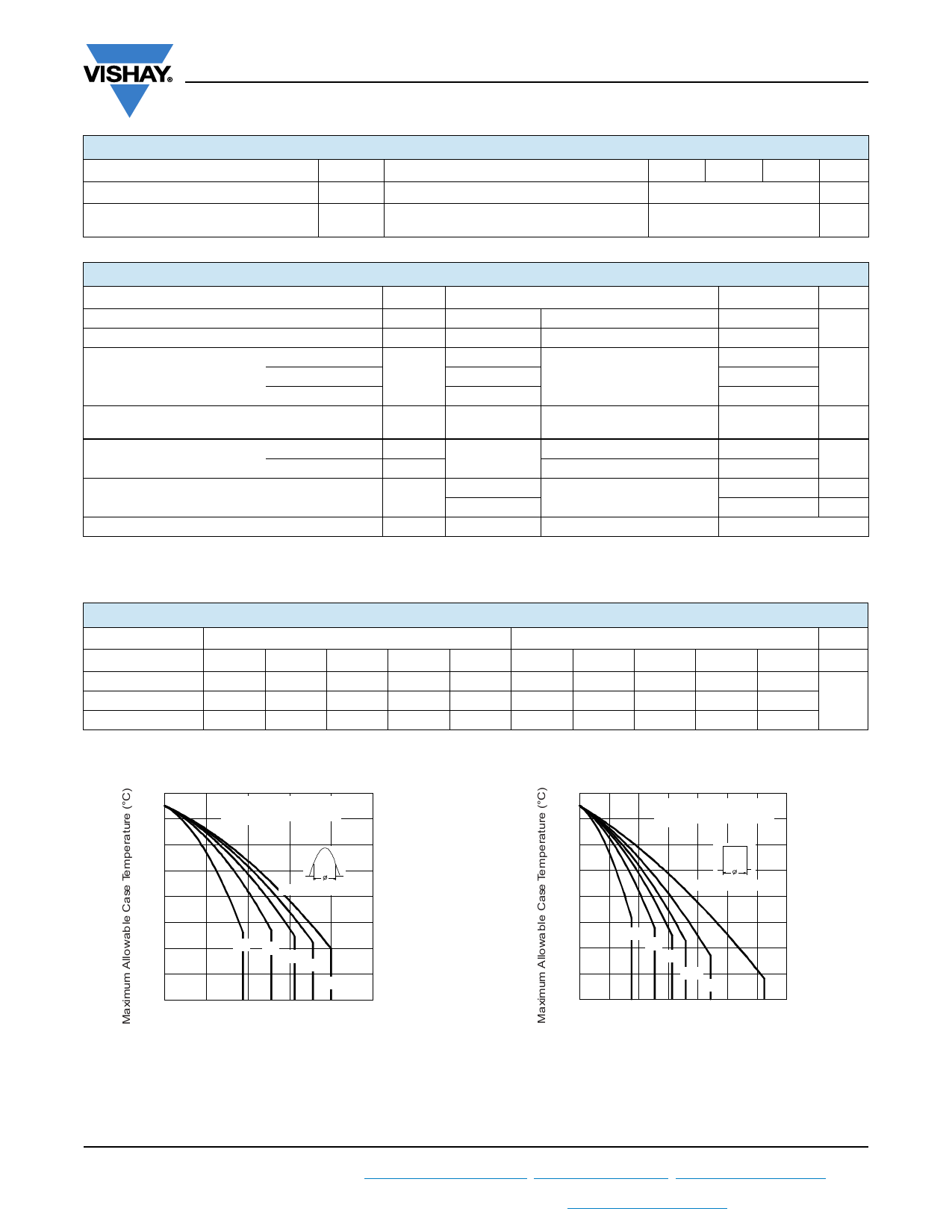
T40HFL.. Series
RthJC (DC) = 0.85 K/ W
Conduc tion Angle
30° 60°
90°
120°
180°
10
20
30
40
50
Average Forward Current (A)
130
120
110
100
90
80
70
60
50
0
T40HFL.. Series
R thJC (DC) = 0.85 K/ W
Conduc tion Period
30°
60°
90°
120°
180° DC
10 20 30 40 50 60 70
Average Forward Current (A)
Fig. 1 - Current Ratings Characteristics
Fig. 2 - Current Ratings Characteristics
Revision: 20-Dec-16
3
Document Number: 93184
For technical questions within your region: DiodesAmericas@vishay.com, DiodesAsia@vishay.com, DiodesEurope@vishay.com
THIS DOCUMENT IS SUBJECT TO CHANGE WITHOUT NOTICE. THE PRODUCTS DESCRIBED HEREIN AND THIS DOCUMENT
ARE SUBJECT TO SPECIFIC DISCLAIMERS, SET FORTH AT www.vishay.com/doc?91000
Share Link: 