AT76C101 Просмотр технического описания (PDF) - Atmel Corporation
Номер в каталоге
Компоненты Описание
Список матч
AT76C101 Datasheet PDF : 13 Pages
| |||
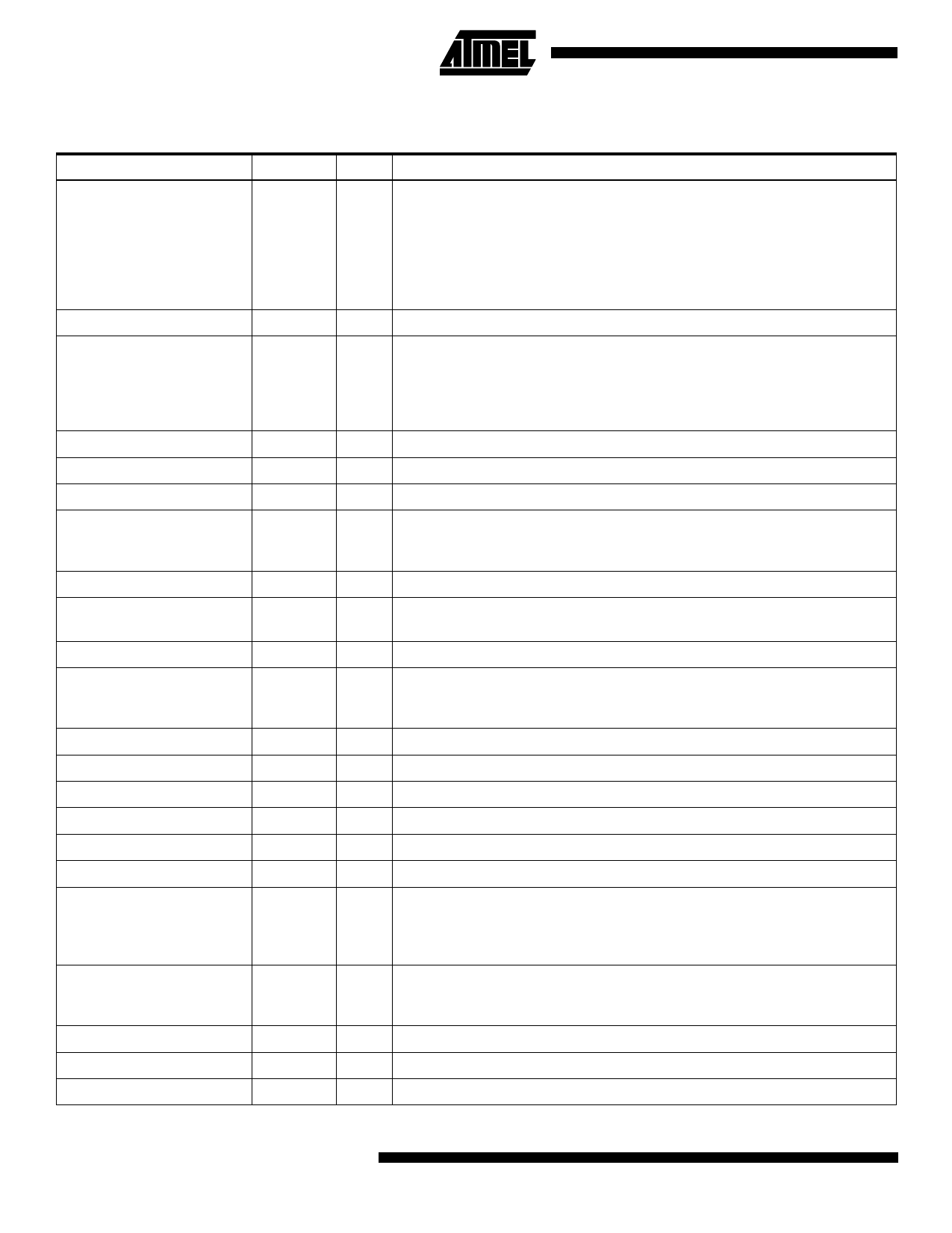
Table 2. Register File Description
Register
Address
HPeriod_Low
0F800
HPeriod_High
HSyncWidth_Low
0F801
0F802
HSyncWidth_High
HDelay_Low
HDelay_High
HActive_Low
HActive_High
VPeriod_Low
VPeriod_High
VSyncWidth_Low
VSyncWidth_High
VDelay_Low
VDelay_High
VActive_Low
VActive_High
Start_Reg
Mode
0F803
0F804
0F805
0F806
0F807
0F808
0F809
0F80A
0F80B
0F80C
0F80D
0F80E
0F80F
0F810
0F812
Int_Table_Load_Enable
0F813
Decoder_Error
Decoder_Error_Code_Low
Decoder_Error_Code_High
0F814
0F815
0F816
R/W Description
R/W HPeriod-low byte (bit 0 to 7).
For color pictures, in Master mode, HPeriod contains one less than the number
of pixels between successive HSYNC pulses. In Slave Mode, it contains the
time between the falling edge of one HSYNC pulse and the start of the next
HSYNC pulse (in terms of pixels).
For grayscale images: set this register to 1 less than half the number of pixels
between successive Hsync pulses.
R/W HPeriod - high byte (bit 8 to 15).
R/W HSyncWidth - low byte. Used only in Master mode.
For color images: 1 less than the number of pixels that Hsync has to be held
active low.
For grayscale images: 1 less than half the number of pixels that Hsync has to
be held active low.
R/W HSyncWidth - high byte.
R/W HDelay - low byte. Delay from falling edge of HSYNC to the first active pixel.
R/W HDelay - high byte.
R/W HActive - low byte.
For color images: size of active horizontal line divided by 8.
For grayscale images: size of active horizontal line in pixels divided by 16.
R/W HActive - high byte.
R/W VPeriod - low byte. Used in Master mode - contains the number of lines in the
frame_7.
R/W VPeriod - high byte.
R/W VSyncWidth - low byte.
Used in Master mode - one less than the number of lines that Vsync has to be
held active low.
R/W VSyncWidth - high byte.
R/W VDelay - low byte.
R/W VDelay - high byte.
R/W VActive - low byte. Number of active vertical lines.
R/W VActive - high byte.
R/W Bit 0 is used to initiate the compression/decompression pipeline.
R/W Determine the device operating mode.
The function of each bit is shown below. Bit 0: Encode(0)/Decode(1) operation.
Bit 1: Color(0)/Grayscale(1) Image. Bit 2: Video Master(1)/Slave(0) Mode.
Rest of bits are reserved and should be set to zero.
R/W Various bits of this register enable loading the different tables on chip. Bit 0:
When set, enables programming the Quantization Tables. Bit 1: When set,
enables loading the Huffman Tables, including the MAXMIN tables.
R The chip sets this register to 1, if an error occurs while decoding.
R Decoder_Error_Code - high byte.
R Decoder_Error_Code - high byte.
10
AT76C101
Share Link: 