LH28F320BJE-PTTL90 Просмотр технического описания (PDF) - Sharp Electronics
Номер в каталоге
Компоненты Описание
Список матч
LH28F320BJE-PTTL90 Datasheet PDF : 51 Pages
| |||
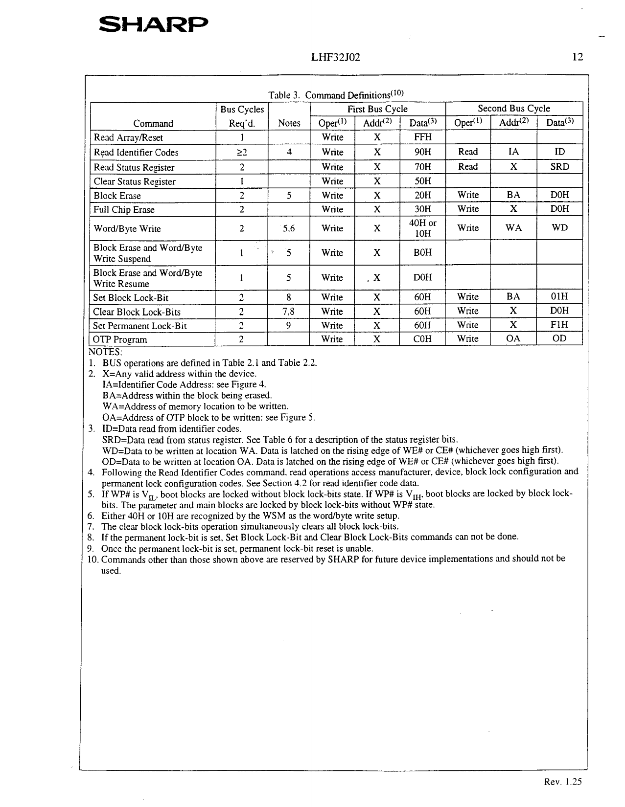
LHF32JO2
Table 3. Command Definition&lo)
--
12
Full Chip Erase
IIWord/Byte Write
2
I2
Block Erase and Word/Byte
1
Write Suspend
Block Erase and Word/Byte
Write Resume
1
Set Block Lock-Bit
2
Clear Block Lock-Bits
2
Set Permanent Lock-Bit
2
OTP Program
2
1 5.6
> .j
5
8
7.8
9
1 Write 1 X
1 Write I x
I
Write
X
Write
,X
Write
X
Write
X
Write
X
Write
X
1 30H 1 Write 1 X
) 4yy~ I Write I WA
BOH
DOH
60H
Write
BA
60H
Write
X
60H
Write
X
COH
Write
OA
) DOH I
/ WD I /
OlH
DOH
FIH
OD
1. BUS operations are defined in Table 2.1 and Table 2.2.
2. X=Any valid address within the device.
IA=Identifier Code Address: see Figure 4.
BA=Address within the block being erased.
WA=Address of memory location to be written.
OA=Address of OTP block to be written: see Figure 5.
3. ID=Data read from identifier codes.
SRD=Data read from status register. See Table 6 for a description of the status register bits.
WD=Data to be written at location WA. Data is latched on the rising edge of WE# or CE# (whichever goes high first).
OD=Data to be written at location OA. Data is latched on the rising edge of WE# or CE# (whichever goes high first).
4. Following the Read Identifier Codes command. read operations access manufacturer, device. block lock configuration and
permanent lock configuration codes. See Section 4.2 for read identifier code data.
5. If WP# is V,, boot blocks are locked without block lock-bits state. If WP# is Vt,, boot blocks are locked by block lock-
bits. The parameter and main blocks are locked by block lock-bits without WP# state.
6. Either 4OH or 10H are recognized by the WSM as the word/byte write setup.
7. The clear block lock-bits operation simultaneously clears all block lock-bits.
8. If the permanent lock-bit is set, Set Block Lock-Bit and Clear Block Lock-Bits commands can not be done.
9. Once the permanent lock-bit is set. permanent lock-bit reset is unable.
10. Commands other than those shown above are reserved by SHARP for future device implementations and should not be
used.
Rev. 1.25
Share Link: 