RV5C386A-E2 Просмотр технического описания (PDF) - RICOH Co.,Ltd.
Номер в каталоге
Компоненты Описание
Список матч
RV5C386A-E2 Datasheet PDF : 42 Pages
| |||
PRELIMINARY
RV5C386A
Calculation example is shown below:
Pull-up resistor (Rp) = 10kΩ, Bus capacity = 50pF(both for SCL, SDA), Vdd=3v,
In a system with sum of input current and off-state output current of each pin = 0.1µA,
I2C-Bus is used for 10ms every second while the rest of 990ms in the stand-by mode,
In this mode, number of transitions of the SCL pin from “H” to “L” state is 100 while SDA 50, every second.
Bus consumption current ≈ 0.1µA×990msec
990msec + 10msec
+
3V × 10msec × 2
10KΩ × 2 × (990msec + 10msec)
+ 3V × 50pF × (100 + 50)
≈ 0.099µA + 3.0µA + 0.0225µA ≈ 3.12µA
Generally, the second member of the above formula is larger enough than the first and the third members,
bus consumption current may be determined by the second member is many cases.
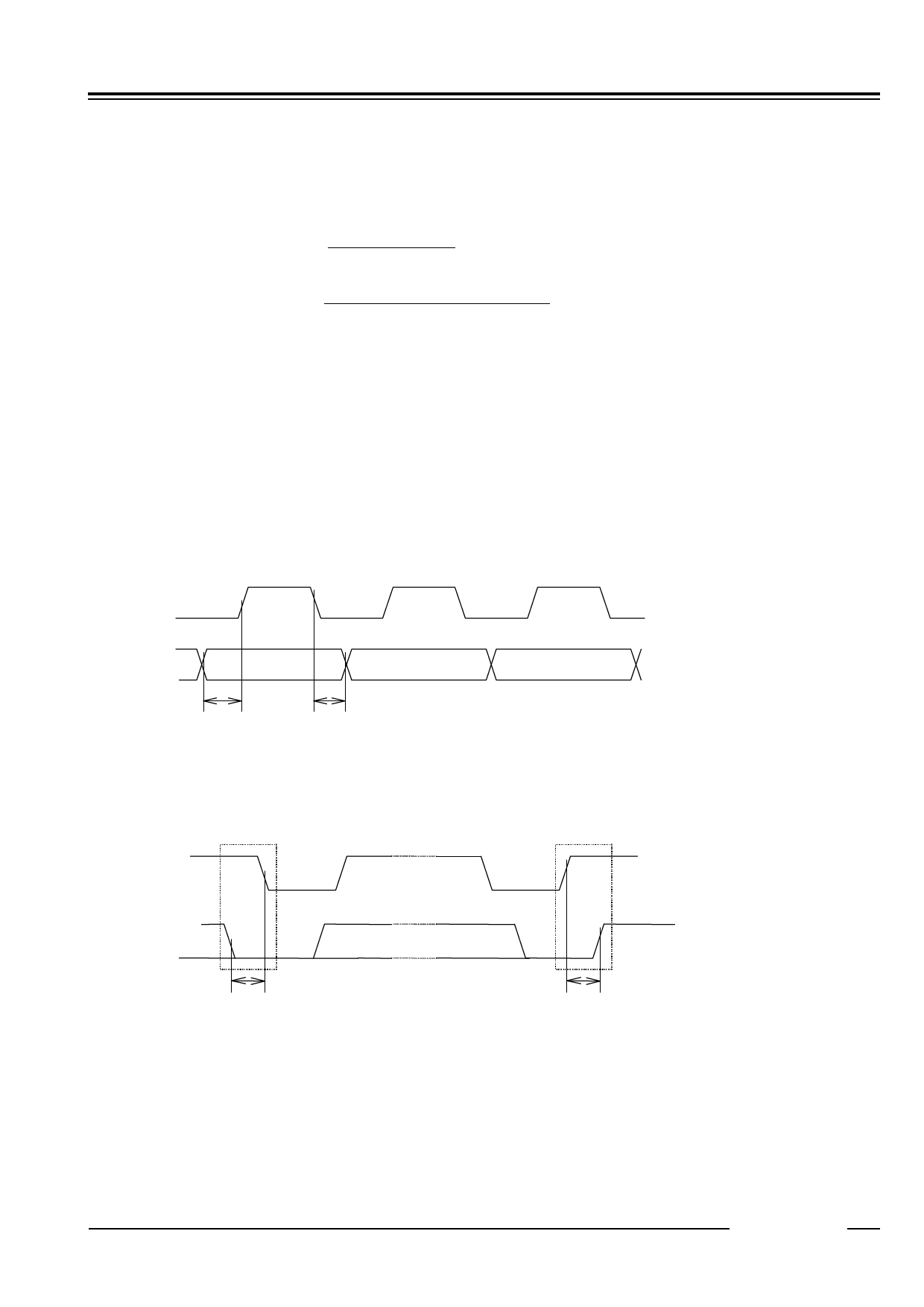
14.1.2. Transmission System of I2C-Bus
(1) Start Condition and Stop Condition
In I2C-Bus, SDA must be kept at a certain state while SCL is at the “H” state during data transmission as
shown below.
SCL
SDA
tSU;DAT
tHD;DAT
The SCL and SDA pins are at the “H” level when no data transmission is made. Changing the SDA from “H” to
“L” when the SCL and the SDA are “H” activates the Start Condition and access is started. Changing the SDA
from “L” to “H” when the SCL is “H” activates Stop Condition and accessing stopped. Generation of Start and
Stop Conditions are always made by the master (see the figure below).
Start Condition
Stop Condition
SCL
SDA
tHD;STA
tSU;STO
(2) Data transmission and its acknowledge
After Start condition is entered, data is transmitted by 1byte (8bits). Any bytes of data may be serially
transmitted. The receiving side will send an acknowledge signal to the transmission side each time 8bit data
is transmitted. The acknowledge signal is sent immediately after falling to “L” of SCL 8bit clock pulses of
data is transmitted, by releasing the SDA by the transmission side that has asserted the bus at that time and
by turning SDA to “L” by receiving side. When transmission of 1byte data next to preceding 1byte of data is
received the receiving side releases the SDA pin at falling edge of the SCL 9bit of clock pulses or when the
receiving side switches to the transmission side it starts data transmission. When the master is receiving
side, it generates no acknowledge signal after last 1byte of data from the slave to tell the transmitter that data
12345
- 19 -
Share Link: 