RV5C386A-E2 Просмотр технического описания (PDF) - RICOH Co.,Ltd.
Номер в каталоге
Компоненты Описание
Список матч
RV5C386A-E2 Datasheet PDF : 42 Pages
| |||
PRELIMINARY
RV5C386A
(5) CT2,CT1, and CT0
CT2 CT1
00
00
01
01
10
10
11
11
Periodic Interrupt Selection Bits
CT0
Description
Wave form mode
Interrupt Cycle and Falling Timing
0
-
OFF(H)
1
-
Fixed at “L”
0 Pulse Mode *1) 2Hz(Duty50%)
1 Pulse Mode *1) 1Hz(Duty50%)
0 Level Mode *2) Once per 1 second (Synchronized with
second counter increment)
1 Level Mode *2) Once per 1 minute (at 00 seconds of every
minute)
0 Level Mode *2) Once per hour (at 00 minutes and 00
seconds of every hour)
1 Level Mode *2) Once per month (at 00 hours, 00 minutes,
and 00 seconds of first day of every month)
(Default)
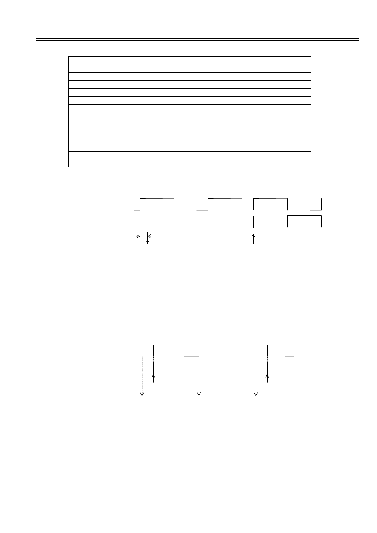
*1) Pulse Mode: 2-Hz and 1-Hz clock pulses are output in synchronization with the increment of the second
counter as illustrated in the timing chart below.
CTFG Bit
/INTRA Pin
Approx. 92µs
(Increment of second counter)
Rewriting of the second counter
In the pulse mode, the increment of the second counter is delayed by approximately 92 µs from the falling edge of
clock pulses. Consequently, time readings immediately after the falling edge of clock pulses may appear to lag
behind the time counts of the real-time clocks by approximately 1 second. Rewriting the second counter will
reset the other time counters of less than 1 second, driving the /INTRA pin low.
*2) Level Mode: Periodic interrupt signals are output with selectable interrupt cycle settings of 1 second, 1
minute, 1 hour, and 1 month. The increment of the second counter is synchronized with the
falling edge of periodic interrupt signals. For example, periodic interrupt signals with an
interrupt cycle setting of 1 second are output in synchronization with the increment of the second
counter as illustrated in the timing chart below.
CTFG Bit
/INTRA Pin
Setting CTFG bit to 0
(Increment of
second counter)
(Increment of
second counter)
Setting CTFG bit to 0
(Increment of
second counter)
*1), *2) When the oscillation adjustment circuit is used, the interrupt cycle will fluctuate once per 20sec. as follows:
Pulse Mode: The “L” period of output pulses will increment or decrement by a maximum of ±3.784 ms. For
example, 1-Hz clock pulses will have a duty cycle of 50 ±0.3784%.
Level Mode: A periodic interrupt cycle of 1 second will increment or decrement by a maximum of ±3.784 ms.
12345
- 11 -
Share Link: 