ZR36016 Просмотр технического описания (PDF) - Zoran Corporation
Номер в каталоге
Компоненты Описание
Список матч
ZR36016 Datasheet PDF : 36 Pages
| |||
Integrated Color Space / Raster-To-Block Converter
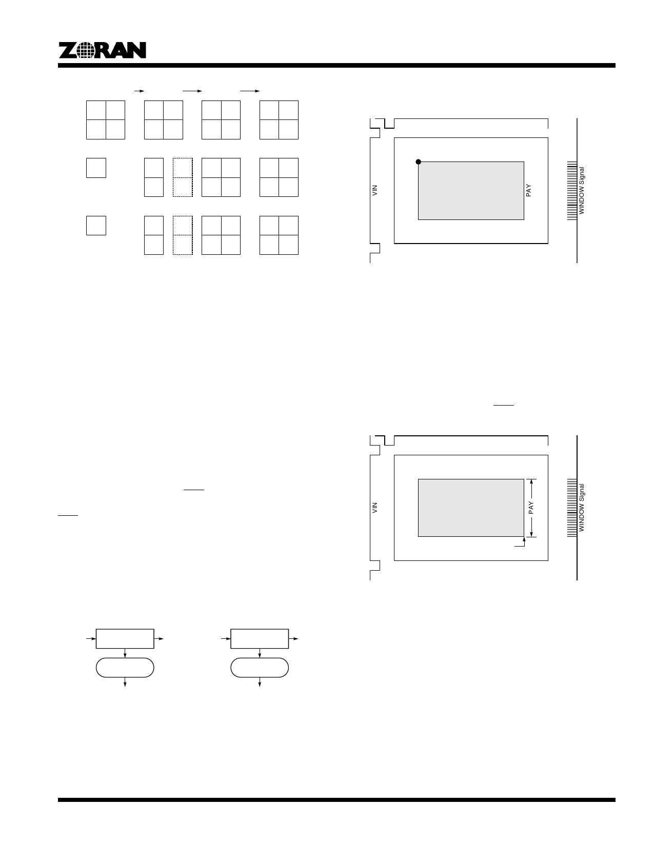
YC 4:1:1 (H2V2)
Y00 Y01
Y10 Y11
YC 4:4:2
Y00 Y01
Y10 Y11
YC 4:4:4
Y00 Y01
Y10 Y11
RGB
R00 R01
R10 R11
Cr00
Cr00
Cr10
Cr02
Cr12
Cr00 Cr01
Cr10 Cr11
G00 G01
G10 G11
is again determined by the MODE and DSPY fields and by the
DSFL bit.
HIN
(NAX, NAY)
Expanded Range from ZR36050
Cb00
Cb00
Cb10
Cb02
Cb12
Cb00 Cb01
Cb10 Cb11
G00 G01
G10 G11
The components in dashed boxes are used when SBFL=1, to
compute Cr01, Cr11, Cb01 and Cb11.
Figure 14. Interpolation Flow
Compression/Expansion
Data Interfaces
The primary data flows are shown in Figure 15 for the compres-
sion and expansion modes. In compression data can be input on
PXIN and be converted and output on PXOUT while also
sending converted data within a window to the ZR36050 for
compression.
For incoming data on PXIN the start of each frame is indicated
by the rising edge of VIN and the start of each line is indicated
by the rising edge of HIN. The active window area for ZR36016
processing starts on line NAY and on pixel NAX on that line. The
processing continues for the window area of PAY lines and PAX
pixels. An end of scan signal EOS is sent to the ZR36050 after
the last pixel in the window is sent on compression. Similarly an
EOS is expected from the ZR36050 on expansion.
Data going directly from PXIN to PXOUT can not be windowed.
It can, however, undergo color space conversion and format
conversion as determined by the MODE and DSPY fields, and
filtering during the format conversion if the DSFL bit is set. The
data is output with VOUT and HOUT after the internal process-
ing delay.
PAX
Input Image from PXIN
Figure 16. Overlay of Expanded Image on PXIN
Data on the PXIN and PXOUT buses are transferred with
PXCLK which has the relationship to the system clock SYSCLK
as shown in Table 8. PXIN, VIN and HIN are clocked with
PXCLK on input and PXOUT, VOUT, HOUT and WINDOW are
clocked with PXCLK on output.
Figure 17 shows the normal processing area in compression
when the value of PAY is known (a non-zero value in the PAY
register) and how WINDOW is active during the processing.
Note where the end of scan signal EOS is generated.
HIN
Processing Area
EOS Output
Figure 17. Normal Processing Area When PAY ≠ 0
PXIN
Color / Format
Conversion
PXOUT PXIN
Color / Format
Conversion
PXOUT
Window
Management
Window
Management
ZR36050
Compression
ZR36050
Expansion
Figure 15. Data Flows Between PXIN, PXOUT and ZR36050
In expansion, the path from PXIN to PXOUT is the same as in
compression. If there is expanded data from the ZR36050 it is
overlayed in the window area as shown in Figure 16. Processing
17
Share Link: 