ZR36016 Просмотр технического описания (PDF) - Zoran Corporation
Номер в каталоге
Компоненты Описание
Список матч
ZR36016 Datasheet PDF : 36 Pages
| |||
Integrated Color Space / Raster-To-Block Converter
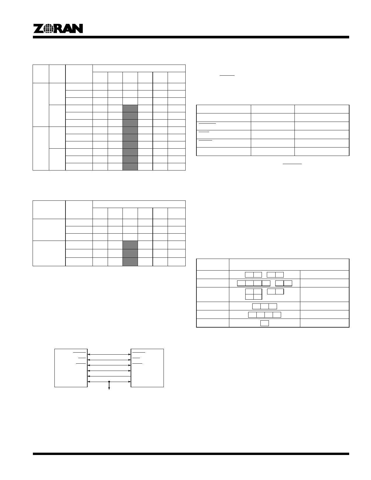
Limitations on the value of PAX are given in Table 18.
Table 18: Limitations on PAX
RSTR
Bit
0
1
HORZ
0
1
0
1
PAX
Max Value
Min Value
Multiple of…
Max Value
Min Value
Multiple of…
Max Value
Min Value
Multiple of…
Max Value
Min Value
Multiple of…
1:0:0
8192
8
8
16348
16
16
65536
8
8
65536
16
16
4:2:2
4096
16
16
8192
32
32
32768
8
8
65536
16
16
ZR36050
4:1:1 4:1:1
(H2V2) (H4V1)
2720 5440
16
32
16
32
8192
32
32
43688
8
8
65536
16
16
4:4:4
2728
8
8
5456
16
16
21840
8
8
43688
16
16
4:4:4:4
2048
8
8
4096
16
16
16348
8
8
32768
16
16
The limitations on PAY when RSTR = 0 are in Table 19.
Table 19: Limitations on PAY
VERT Bit
0
1
PAY
Max Value
Min Value
Multiple of…
Max Value
Min Value
Multiple of…
1:0:0
65536
8
8
65536
4:2:2
65536
8
8
65536
ZR36050
4:1:1 4:1:1
(H2V2) (H4V1)
65536 65536
16
8
16
8
65536
4:4:4
65536
8
8
65536
4:4:4:4
65536
8
8
65536
16
16
16
16
16
16
16
16
16
16
In the case of RSTR = 1, the maximum value of PAY is 65536 in
any format. The minimum value is 1 when VERT = 0 and is 2
when VERT = 1.
ZR36050 Bus Interface
The ZR36016 connects directly with the ZR36050 as shown in
Figure 30. The data transfer rate on BDATA(7:0) is always at the
SYSCLK clock rate regardless of the format.
register in the ZR36016. These two conditions are shown in
Table 20.
If the ZR36016 is set for compression in the Mode register and
receives a low input on COMP indicating expansion it will output
an active STOP provided it is not already processing.
Table 20: Directional Status of ZR36016 Pins on the
ZR36050 Interface
Pin
COMP
DSYNC
EOS
STOP
BDATA(7:0)
Compression
IN High
OUT
OUT
IN
OUT
Expansion
IN Low
INT
IN
OUT
IN
For transfers with the ZR36050 the DSYNC signal is treated as
a pixel enable when RSTR = 1 for raster-to-raster transfers
rather than as a block enable for block transfers. See the
ZR36050 User’s Manual for its timing information.
JPEG MCU (Minimum Coded Unit) Structure
Data transfer between the ZR36016 and the ZR36050 is always
in units of the MCU. The structure of the MCU for each of the
supported compressed data formats is shown in Table 21. For
baseline compression, the entities of the MCU are 8x8 blocks;
for lossless and fast preview, they are individual samples.
Table 21: MCU Structure
ZR36050
Image Format
4:2:2
4:1:1 (H4V1)
4:1:1 (H2V2)
4:4:4
4:4:4:4
4:0:0
MCU Structure
Y0 Y1 Cb0 Cr0
Y0, Y1, Cb0, Cr0
Y0 Y1 Y2 Y3 Cb0 Cr0
Y0, Y1, Y2, Y3, Cb0, Cr0
Y0 Y1
Y2 Y3
Cb0 Cr0
Y0, Y1, Y2, Y3, Cb0, Cr0
R0 G0 B0
C0 M0 Y0 K0
Y0
R0, G0, B0
C0, M0, Y0, K0
Y0
ZR36016
DSYNC
EOS
STOP
BDATA[7:0]
COMP
SYSCLK
ZR36050
DSYNC
EOS
STOP
BDATA[7:0]
COMP
DCLK
System Clock
Figure 30. ZR36016 to ZR36050 Connections
The direction of the bidirectional pins on the ZR36016, and
therefore possible transfers, is determined by the COMP input
signal from the ZR36050 rather than the CMPR bit of the Mode
21
Share Link: 