AN1042 Просмотр технического описания (PDF) - ON Semiconductor
Номер в каталоге
Компоненты Описание
Список матч
AN1042 Datasheet PDF : 12 Pages
| |||
AN1042/D
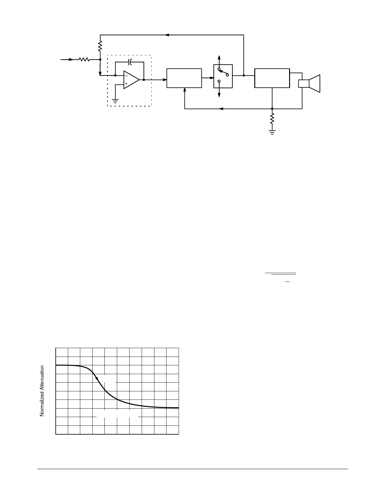
Input
R5
R4
+44 V
Integrator
Switch
Controller
±2 V
Error
Current
Voltage
Sense
–44 V
Output
Switch
Low Pass
Filter
8Ω
Speaker
R27
Figure 2. Block Diagram of Class D Amplifier
The switch controller has three main functions. First, it
insures that the output duty cycle is never less than 5% or
greater than 95%. This is made necessary by the use of ac
coupling for the drive. Second, it controls the output duty
cycle in response to the error voltage input. This duty cycle
is a linear function of the error voltage input. Third, it
provides short circuit protection to the amplifier in
response to the current sense input. If overcurrent is
detected, the error voltage input will be overridden and the
amplifier output voltage reduced as necessary to bring the
current back within limits.
A class B analog amplifier has a theoretical efficiency of
78.5% when producing a sine wave at the point of clipping.
A switching amplifier, or so called class D amplifier, must do
much better to justify its extra complexity. The switching
amplifier described in this paper achieves an efficiency of
92% at its rated power of 72 watts. Its efficiency peaks at
95% for 30 watts output and falls to 50% for 1.5 watts
output. These efficiencies result from the good performance
of TMOS power MOSFETs at high switching frequencies
and the simplicity of complementary drive circuitry.
Above the 100 watt level, a switching amplifier costs less
than a conventional amplifier although it is slightly more
complex. The heatsink size is about one–tenth and the
weight is about one–fourth that of a class B amplifier.
1.0
0.8
–3 dB
0.6
0.4
0.2
0
Frequency (kHz)
0
12
24
36
48
60
Figure 3. 20 kHz Butterworth Filter Frequency
Response
A switching amplifier must switch at a frequency well
above the highest frequency to be reproduced. A low pass
filter must follow the switching stage to eliminate the high
frequency square waves and pass the audio to the speaker.
High switching frequencies can simplify filter design, but
cause excessive losses in the switching devices. Low
switching frequencies limit the upper frequency response
of the amplifier and complicate filter design. The amplifier
described in this paper operates at a switching frequency of
120 kHz. Its response extends down to dc, with an upper
–3 dB point of 20 kHz.
The filter chosen here is a 4 pole Butterworth Low Pass
which is maximally flat in the passband. It is designed to
be driven by a voltage source and loaded into 8 ohms. This
type of filter has a transfer function of
Ǹ E +
1
1
)
ǒ f Ǔ8
fc
where f is the frequency of interest and fc is the cutoff
frequency. At the 120 kHz switching frequency, this filter
has a voltage attenuation of 62 dB. With a ±44 volt square
wave into the filter at 120 kHz, the maximum residue is a
sine wave of about 30 millivolts rms. The filter is only 0.1 dB
down at 12.5 kHz and 1 dB down at 17 kHz as shown in
Figure 3. The –3 dB point is 20 kHz.
The frequency response of the filter will be flat only if it
is properly loaded into 8 ohms. A 16 ohm speaker load will
cause high frequency peaking and a 4 ohm speaker will
cause high frequency loss. The output impedance of the
filter changes across the band as shown in Figure 4. It
exhibits a parallel resonance at 11.4 kHz and 35.2 kHz, and
a series resonance at 20 kHz. In practice, these resonances
cause no difficulty with typical speakers and crossover
networks.
This amplifier and a high quality conventional amplifier
were both fed pink noise while driving full range speakers.
A broad band audio spectrum analyzer with a calibrated
microphone was used to measure sound pressure level. The
difference in sound pressure level between the two, if any,
was well under 1 dB from 60 Hz to 16 kHz.
http://onsemi.com
2
Share Link: 