CDP1020 Просмотр технического описания (PDF) - Intersil
Номер в каталоге
Компоненты Описание
Список матч
CDP1020 Datasheet PDF : 23 Pages
| |||
CDP1020
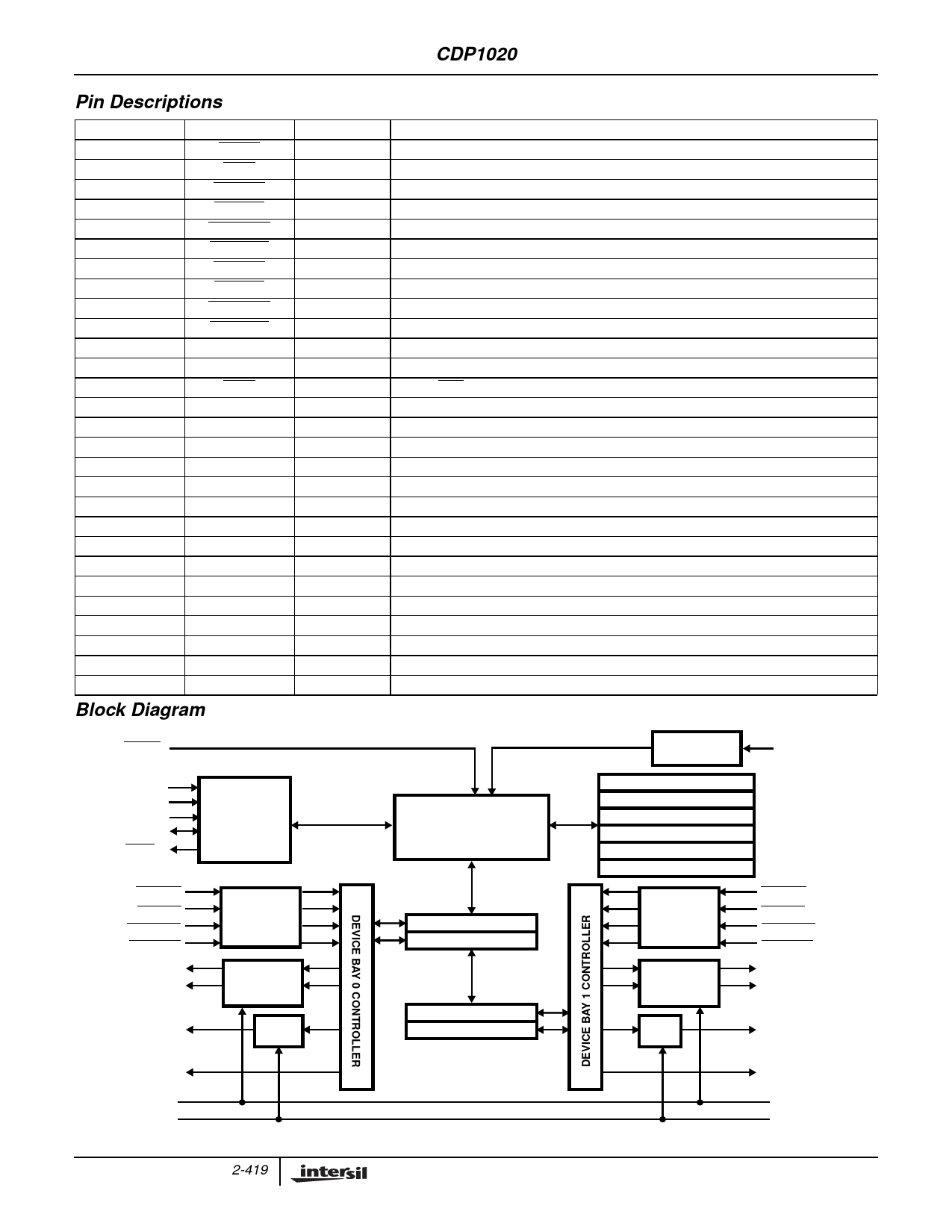
Pin Descriptions
PIN NUMBER
1
2
3
4
5
6
7
8
9
10
11
12
13
14
15
16
17
18
19
20
21
22
23
24
25
26
27
28
PIN NAME
RESET
TEST
1394PR0
USBPR0
REMREQ0
SECURE0
1394PR1
USBPR1
REMREQ1
SECURE1
SDA
SCK
ALRT
VGATE
PWREN0
PWREN1
SFTLOCK0
SFTLOCK1
LEDG0
LEDA0
LEDG1
LEDA1
VLED
VDD
VSS
CLK
AD0
AD1
Block Diagram
RESET
IN/OUT
IN
-
IN
IN
IN
IN
IN
IN
IN
IN
IN/OUT
IN/OUT
OUT
-
OUT
OUT
OUT
OUT
OUT
OUT
OUT
OUT
-
-
-
IN
IN
IN
AD1
AD0
SCK
SDA
ALRT
I 2C/SMBus
INTERFACE
1394PR0
USBPR0
REMREQ0
SECURE0
LEDA0
LEDG0
PWREN0
SFTLOCK0
VLED
VGATE
DEBOUNCE
LOGIC and
PULLUP Rs
TIMER/
LEVEL
SHIFTER
LEVEL
SHIFT
PIN DESCRIPTION
Device Bay Controller Master Reset Schmitt Input
Test pin used by manufacturer only. Must be externally connected to VDD
Bay 0 1394 Presence Input with Active Pull-up
Bay 0 USB Presence Input with Active Pull-up
Bay 0 Remove Request Input with Active Pull-up
Bay 0 Security Input with Active Pull-up
Bay 1 1394 Presence Input with Active Pull-up
Bay 1 USB Presence Input with Active Pull-up
Bay 1 Remove Request Input with Active Pull-up
Bay 1 Security Input with Active Pull-up
SMBus/I2C Data Schmitt Input/Open-Drain Output
SMBus/I2C Clock Schmitt Input/Open-Drain Output
SMBus Alert Open-Drain Output
Power Supply Input for PWREN0/PWREN1 Drivers
Bay 0 Power Enable 12V NMOS Gate Drive Output
Bay 1 Power Enable 12V NMOS Gate Drive Output
Bay 0 Software Controlled Lock Mechanism Driver
Bay 1 Software Controlled Lock Mechanism Driver
Bay 0 Status Indicator (Green LED) Driver
Bay 0 Status Indicator (Amber LED) Driver
Bay 1 Status Indicator (Green LED) Driver
Bay 1 Status Indicator (Amber LED) Driver
Power Supply Input for LED Driver (LEDAx, LEDGx)
Power Supply Input (Power)
Power Supply Return (Ground or GND)
External Clock Schmitt Input (for RC oscillator)
SMBus/I2C Address Configuration Bit 0
SMBus/I2C Address Configuration Bit 1
DEVICE BAY
CONTROLLER LOGIC
BSTR0 - $10
BCER0 - $14
BSTR1 - $18
BCER1 - $1C
OSCILLATOR
CIRCUITRY
VENDOR - $00
REVISION - $04
SUBSYS VENDOR - $08
SUBSYS REV- $0A
DBCCR - $0C
SFR - $FC
DEBOUNCE
LOGIC and
PULLUP Rs
TIMER/
LEVEL
SHIFTER
CLK
1394PR1
USBPR1
REMREQ1
SECURE1
LEDA1
LEDG1
LEVEL
SHIFT
PWREN1
SFTLOCK1
VLED
VGATE
2-419
Share Link: 