M65762FP Просмотр технического описания (PDF) - MITSUBISHI ELECTRIC
Номер в каталоге
Компоненты Описание
Список матч
M65762FP Datasheet PDF : 28 Pages
| |||
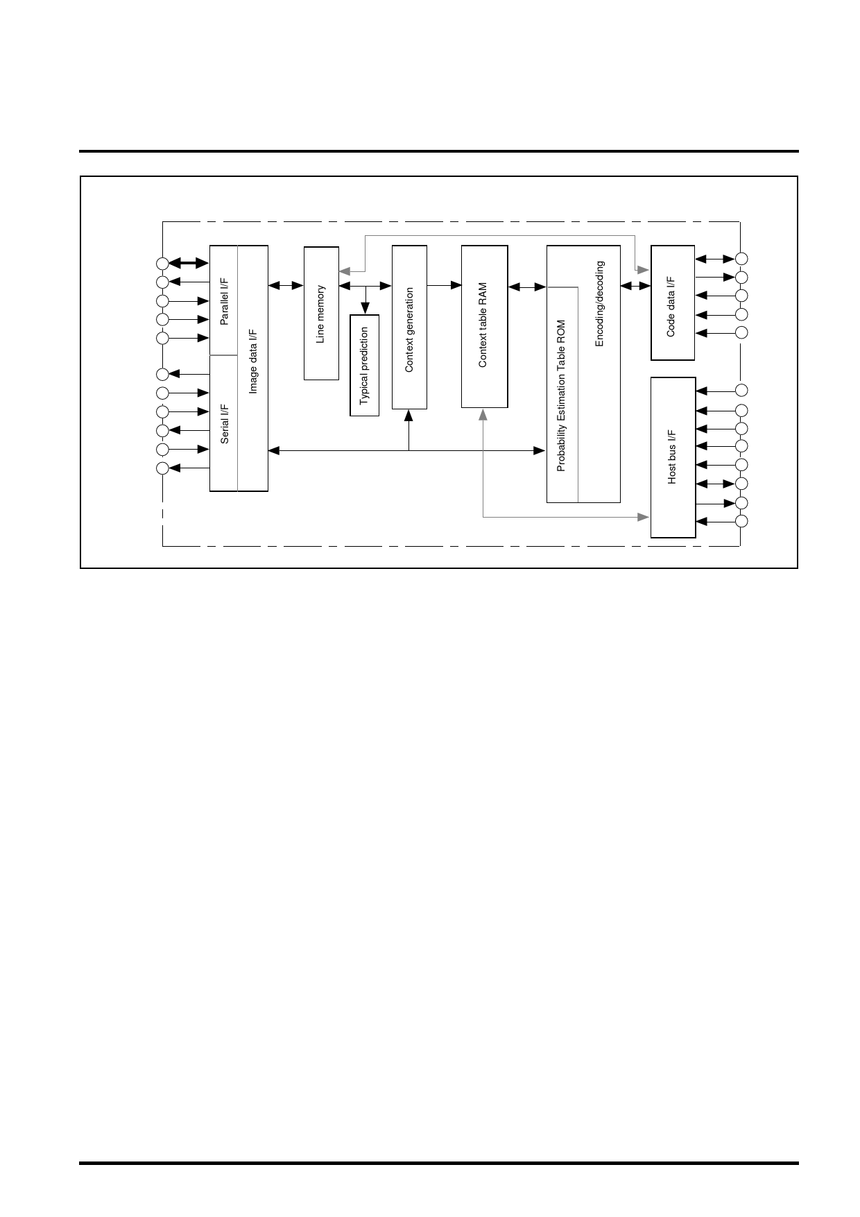
BLOCK DIAGRAM
MITSUBISHI SEMICONDUCTOR (LSI)
M65762FP
QM-CODER
PD0-31
PDRQ 48
PDAK* 49
PDRD* 50
PDWR* 51
PRDY* 54
PTIM* 55
PXCK* 56
PXCKO* 59
SVID* 57
RVID* 58
Pixel data
CD0-31
108 CDRQ
109 CDAK*
110 CDRD*
111 CDWR*
132 RESET*
135 HCS*
HA0-3
134 HWR*
133 HRD*
HD0-7
112 INTR
129 MCLK
(Asterisk "*" indicates negative logic.)
Description on Block Functions
(1) Host bus I/F block
This bus is used to set command parameters and load the
status between the MPU and this block. It is 8-bit bus, This
block is also available to load and store of context table RAM
via the host bus.
(2) Code data I/F block
Bus for input/output of coding data. For the bus width, 32-
bits, 16-bits or 8-bits can be selected.
Image data can also be transferred (in through mode)
between the Image data I/F and this block via built-in line
memory. FIFO buffer for 16 bytes are provided in the code
data I/F block.
(3) Image data I/F block
The Image data I/F is used for input/output of binary image
data. The 32-/16-bit parallel I/F or serial I/F can be selected.
Selection of the serial I/F transfers data in units of 1 pixel in
synchronization with the line, using the handshake signal
(PRDY*, PTIM*).
Selection of parallel I/F uses an external DMA controller for
DMA transfer (in units of stripe).
The image data I/F provides a function for scale-down of
length and breadth by 1/2 in coding and a function for scale-
up of length and breadth by twice in decoding.
(4) Line memory block
4K-byte memory. This block can be set to a maximum of
8192 pixels/line for 3-line template and can be set to a
maximum of 10240 pixels/line for 2-line template. A line is
used for input/output processing of image data to/from
outside and the other lines (2 or 3 lines) are used for
encoding/decoding processing. These two processes can be
independently carried out in synchronization with each line.
The contents of line memory can be loaded or stored via
the image data I/F or coding data I/F.
(5) Typical prediction block
In the typical prediction mode, compares the encoding/
decoding process line agree with the immediately preceding
line and generates pseudo-pixel (SLNTP).
(6) Context generator
By using the 10 pixel template of 2-lines or 3-lines.(including
AT pixel) the standard context minimum of JBIG is generated
with the resolution.
(7) Context table RAM block
Corresponds to the 10-bit standard context. This block can
initialize, load and store the context table RAM.
(8) Coding/decoding block
This block performs arithmetic coding and decoding.
It contains a ROM which contains a table capable of
estimating 113 states and is capable of byte stuffing function
('OO' byte insertion/rejection) and is capable of end marker
code control (Marker insertion/detection).
Share Link: 