LXE1686-0X Просмотр технического описания (PDF) - Microsemi Corporation
Номер в каталоге
Компоненты Описание
Список матч
LXE1686-0X Datasheet PDF : 15 Pages
| |||
LXE1686-0x
INVERTER EVALUATION BOARD
combination op-amp/integrator conditioning circuit as
well.
An optional open/short lamp timeout-disable
comparator circuit is also available, and can be
implemented with one jumper placement at RJ8.
Inverter board is pre-configured to deliver from 3 to
18mArms lamp current, adjustable via the Current
ADJ on board multi-turn potentiometer (R11B).
Inverter board is pre-configured to operate from 65 to
75kHz lamp current, adjustable via the FREQ ADJ on
board multi-turn potentiometer (R10B).
Three critical inverter setup probe test points are
provided, including twenty-seven information test
points to help you design as well as understand the
LMI LX1686 inverter operating concept. Oscilloscope
pictures of typical inverter waveforms at a number of
these test points are also provided for reference.
3. BOARD SETUP PROCEDURE, CRITERIA &
OPTIONS
BASIC INPUT/OUTPUT INTERCONNECTS & MEASUREMENT
Ground panel frame to electrical system ground. If
panel is an STN style LCD, apply a blank (white)
screen video for light measurements.
Determine your method of lamp current
measurement; current probe, percentage of inverter
input power to known lamp power (~ 120%) or known
light output for a given lamp current. If using the light
output measurement, allow for CCFL temperature
stabilization (usually 20 to 40 minutes).
Setup inverter for nominal application system logic
supply voltage at ‘VIN LOGIC’ & ‘PWR GND’
terminals.
Simulate application system main power source with
a variable power supply that can be adjusted over the
full variation range of the application system at ‘VIN
POWER’ & ‘PWR GND’ terminals. Adjust ‘BRITE ADJ’
R30B full clockwise for maximum brightness
condition.
Adjust ‘FREQ ADJ’ R10B for desired lamp current
operating frequency (70kHz nominal).
Establish the lowest main input voltage (VIN POWER)
where target design lamp current, input power or light
output can be maintained. This will require an initial
high ‘Current ADJ’ setting at R11B (full clockwise) to
gain maximum inverter drive capability. Optimum
transformer turns ratio selection is achieved when
lowest main input voltage is that of the lowest
application system potential, where design target
condition are maintainable. Decrease ‘Current ADJ’
R11B until noted reference begins to decrease at
lowest input voltage condition.
Ideally, use the light output reference measurement
for final setting as follows; increase inverter input
voltage to the midrange or nominal input power
potential. Readjust ‘Current ADJ’ R11B until reference
light output level condition is re-established.
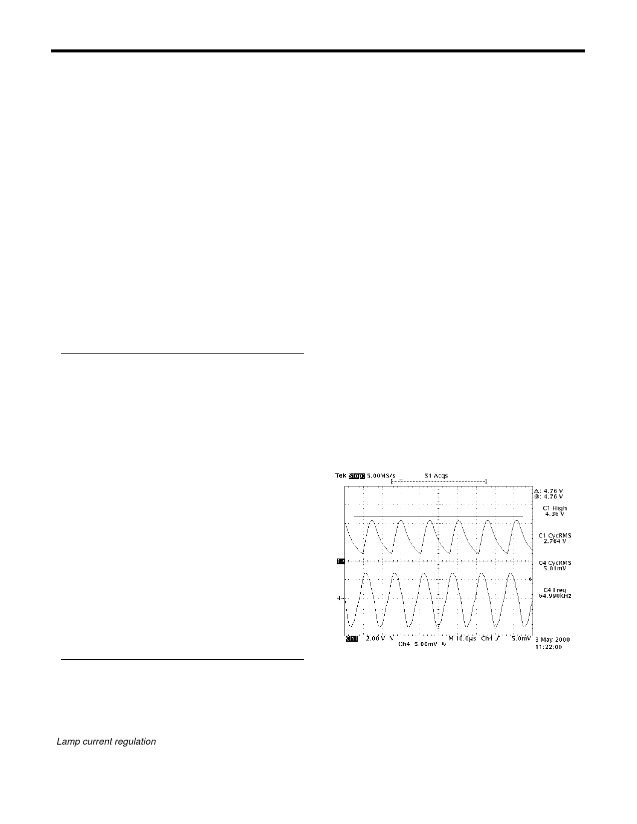
Using an O-scope probe, determine the dc potential
at P4. This DC potential is the equivalent to the
'common-mode' threshold voltage of the lamp current
regulation op-amp. Make a reference of this potential
on the scope scale gradient and place the scope
probe on TP2. Observe TP2 waveform over the entire
main input supply range. The end goal will be to
achieve an AC waveform peak on P2 that doesn't
exceed the DC reference potential, but ideally rides
just below it. In the scope shot below the bar indicates
the level at P4 (VDD) channel 1 is TP2 (ISNS) and
channel 4 show the output current low return side.
Note that the peak value of TP2 is below the P4 level.
In this scope shot the main input supply was at the
nominal input voltage, not the extremes.
RECOMMENDED LAMP CURRENT OPERATING FREQUENCY
Recommended operating frequencies for the LMI
magnetic types: 70 to 100kHz for 2.4 and 4.0Watt, 65
to 75kHz for 7.0Watt. C6 may be reduced in value
(120pF provided as spare component C26) to obtain
a higher operating frequency range.
Lamp current regulation
To reduce TP2 peak amplitude, increase C13 (2.2nF)
value or vise-versa (this will change lamp current
setting, requiring readjustment of ‘Current ADJ’
R11B). Observe light output over the entire inverter
input supply range. Light output variations over low to
high supply condition may be balanced out by varying
the ratios of R11A + R11B to R18. Often R18 is not
needed to accomplish balanced light output, but when
Copyright © 2000
Rev 1.0c, 2000-08-31
Page 6
Share Link: 