ZR36050 Просмотр технического описания (PDF) - Zoran Corporation
Номер в каталоге
Компоненты Описание
Список матч
ZR36050 Datasheet PDF : 52 Pages
| |||
ADVANCE INFORMATION
ZR36050
In JPEG Baseline compression, the Encoding Unit reads the
DCT coefficients from the Block Buffers in the JPEG zig-zag
sequence and quantizes them using the tables in the Quantiza-
tion Table Store. The Quantization Table Store holds up to four
quantization tables. Each component of the image is assigned
one of the quantization tables; this assignment is specified in the
JPEG frame header.
The Encoding Unit encodes the difference of the quantized DC
coefficients of the current and previous blocks, using one of the
DC tables in the Huffman Table Store. After accumulating runs
of zero-valued AC coefficients, it encodes the zero run lengths
and the non-zero AC coefficients using the AC tables in the
Huffman Table Store. The Huffman Table Store has space for
two DC Huffman tables and two AC Huffman tables. Each com-
ponent of a scan is assigned to one DC table and one AC table;
this assignment is specified in the JPEG scan header.
Quantization tables are not used in Lossless compression. In
this mode of operation, the Encoding Unit performs one-dimen-
sional, horizontal predictive coding and Huffman coding of the
samples, similar to that of the DC coefficients in Baseline
compression.
When it has generated a Huffman code, or when it is transferring
the marker segment data, the Encoding Unit writes the com-
pressed data into the Code Buffer. From there, the compressed
data is transferred out of the device, either via the Compressed
Data Interface, or via the Host Interface.
The procedure for JPEG Baseline or Lossless image expansion
is the inverse of the corresponding compression procedure
When expanding an image, the Encoding/Decoding Unit detects
and decodes all the markers and marker segment parameters
included in the compressed data. The host does not need to
extract or decode parameters, such as tables, from the JPEG
compressed data file, since this is done automatically.
Compressed Data Interface
The Compressed Data Interface is the fastest means of transfer-
ring the compressed data into or out of the ZR36050, therefore
it could be used in a motion video compression application,
(Refer to the example shown in Figure 3). Since it can optionally
be configured to operate with up to seven internally generated
wait states, it is also suitable for use with a slow compressed
data store, such as a memory card. When the Compressed Data
Interface is being used, it transfers data in a Master mode,
driving the access control signals to an external auto-increment-
ing (e.g. FIFO) memory device.
Host Interface
If the ZR36050 is configured to transfer the compressed data via
the Host Interface, it can do so in one of two submodes. Slave or
DMA modes. The principal function of the Host Interface is to
allow the host to access the Internal Memory. This access is
required in order to program the operating mode of the device,
specify the JPEG marker segments and their parameters for
compression, initiate the encoding or decoding operation and
read the status of the device.
Internal Memory
The Internal Memory is partitioned into a Control Registers
Section and a JPEG Marker Segments Section.
The Control Registers Section contains the various configuration
registers, status registers for interaction with the host, and infor-
mational registers that provide feedback to the host after the
completion of an operation by the ZR36050.
The Marker Segments Section is where the host writes the
contents of the JPEG marker segments before initiating com-
pression of an image or changing markers between the frame
and scan marker, or between scans. After an expansion, it
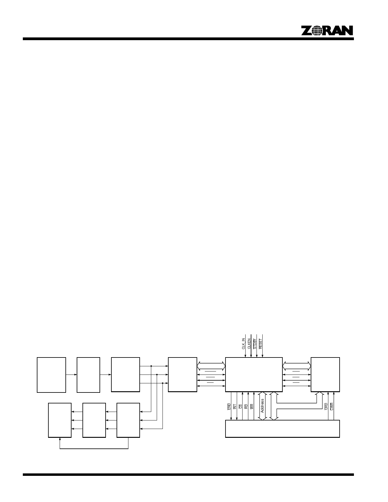
Composite
Video Source
A/D
Y
Digital
Composite U
Video
Decoder
V
Strip Buffer,
Raster to Block
Converter
PIXEL
DSYNC
STOP
EOS
ZR36050
JPEG Image Processor
CODE
CWE
COE
CCS
Compressed
Data FIFO
Display
R
Triple D/A
G & YUV to
B
RGB
Y
U Display
Controller
V
Data
Interface to Computer Peripheral Bus
SYNC
Figure 3. Typical Motion JPEG Compression/Expansion System Configuration
8
Share Link: 