ZR36050 Просмотр технического описания (PDF) - Zoran Corporation
Номер в каталоге
Компоненты Описание
Список матч
ZR36050 Datasheet PDF : 52 Pages
| |||
ADVANCE INFORMATION
ZR36050
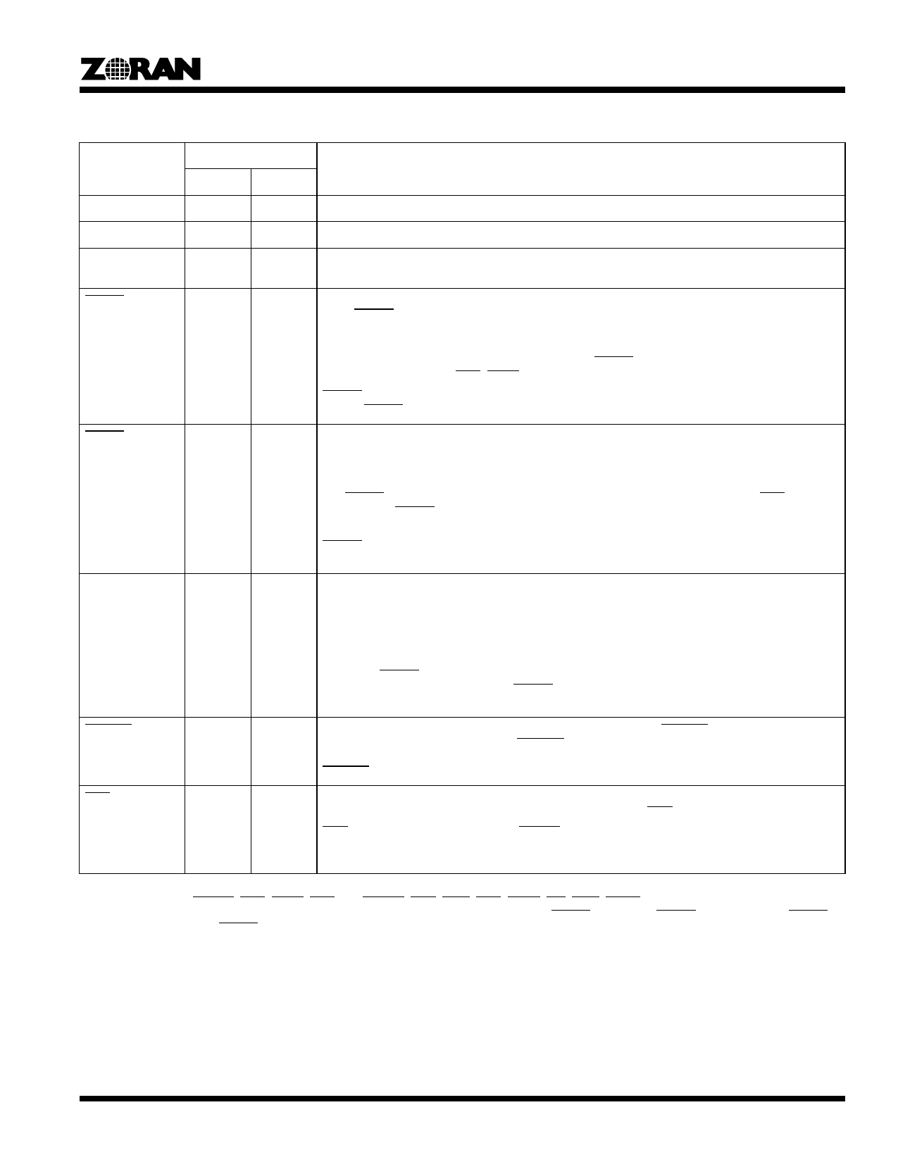
Table 1. Signal Description1, 2
Type3
Signal
Encode Decode
Description
VCC
S
S
+5 volt Power supply. All VCC pins must be connected to +5V.
VSS
S
S
Ground. All VSS pins must be connected to GND.
CLK_IN
I
I
Data Transfer Clock. Provides data transfer timing for the device. All timing is referenced to the rising
edge of this clock.
RESET
I
I
Reset. This active-low input signal resets all the internal controls and places the ZR36050 in the Idle
state. RESET can be activated only when CLKEN is asserted and must remain active for a minimum
of four CLK_IN cycles.
The STATUS_0, INT_REQ_0, and INT_REQ_1 register bits are reset by this signal. The STATUS_1
bits except the END bit are reset; the END bit is set. RESET initializes the ZR36050 to the compres-
sion mode, and activates END, STOP and COMP.
RESET can be activated during the Standby state; in this case the device draws normal current as
long as RESET is active.
STDBY
I
I
Standby. This active-low input signal places the ZR36050 in the Standby state. If CLKEN is active,
only the internal clock circuit consumes power. If CLKEN is inactive in the Standby state, the device
power consumption is further reduced.
The ZR36050 should be switched to the Standby state only when it is in the Idle state: after activation
of a RESET and prior to loading the Internal Memory, or after the ZR36050 issues an END. If CLKEN
is active, then STDBY should be deasserted at least four CLK_IN cycles before accessing the Internal
Memory.
RESET can be activated during the Standby state, only when CLKEN is active. Reading from or
writing to the Internal Memory during the Standby state is prohibited.
CLKEN
I
I
Clock Enable. This active-high input signal enables the data transfer clock CLK_IN, and the internal
PLL that generates an internal double-frequency clock. When inactive, this signal reduces power
further in the Standby state by deactivating the internal clock. The frequency of CLK_IN must be
stable before CLKEN is activated. Furthermore, 5000 CLK_IN cycles are required for the PLL to sta-
bilize, after CLKEN has been activated and before the device is ready for operation.
If the frequency of CLK_IN is changed without turning off the power, then CLKEN must be reactivat-
ed. When STDBY is high, this pin should also be high. For systems in which the 5000 CLK_IN
recovery time is not significant, the STDBY and CLKEN pins can be tied together to the external
standby signal.
FREEZE
I
I
Freeze. This active-low input signal freezes all chip operations. FREEZE is sampled on the rising
edge of CLK_IN. Immediately after FREEZE is sampled, all buses float and all activities of the
ZR36050 are frozen in their current state. All activities resume normally following the deassertion of
FREEZE.
END
O
O
End Of Process. This active-low output signal indicates the normal end of an encoding or decoding
process. If an encoding process ends because of an overflow, END is not activated.
END is activated after activation of RESET and at the completion of an encoding or decoding
process. It stays activated until a GO command is issued or the STATUS_1 register in the Internal
Memory is read.
1. The DATA, CODE, PIXEL, and COEF buses have internal pull-downs that provide 50 microamps of pull-down current at 0.4 volts.
2. The control pins: DSYNC, EOS, STOP, END, CL, CSYNC, COE, CWE, CCS, CAEN, INT, DINT, DREQ and COMP, have internal pull-up
devices that provide 50 microamps at 2.4 volts. These pull-ups are turned on only when STDBY is active but RESET is inactive. When STDBY
is active together with RESET, the above control pins float.
3. I = Input, O = Output, B = Bidirectional, S = Supply.
3
Share Link: 