ZR36050 Просмотр технического описания (PDF) - Zoran Corporation
Номер в каталоге
Компоненты Описание
Список матч
ZR36050 Datasheet PDF : 52 Pages
| |||
ADVANCE INFORMATION
ZR36050
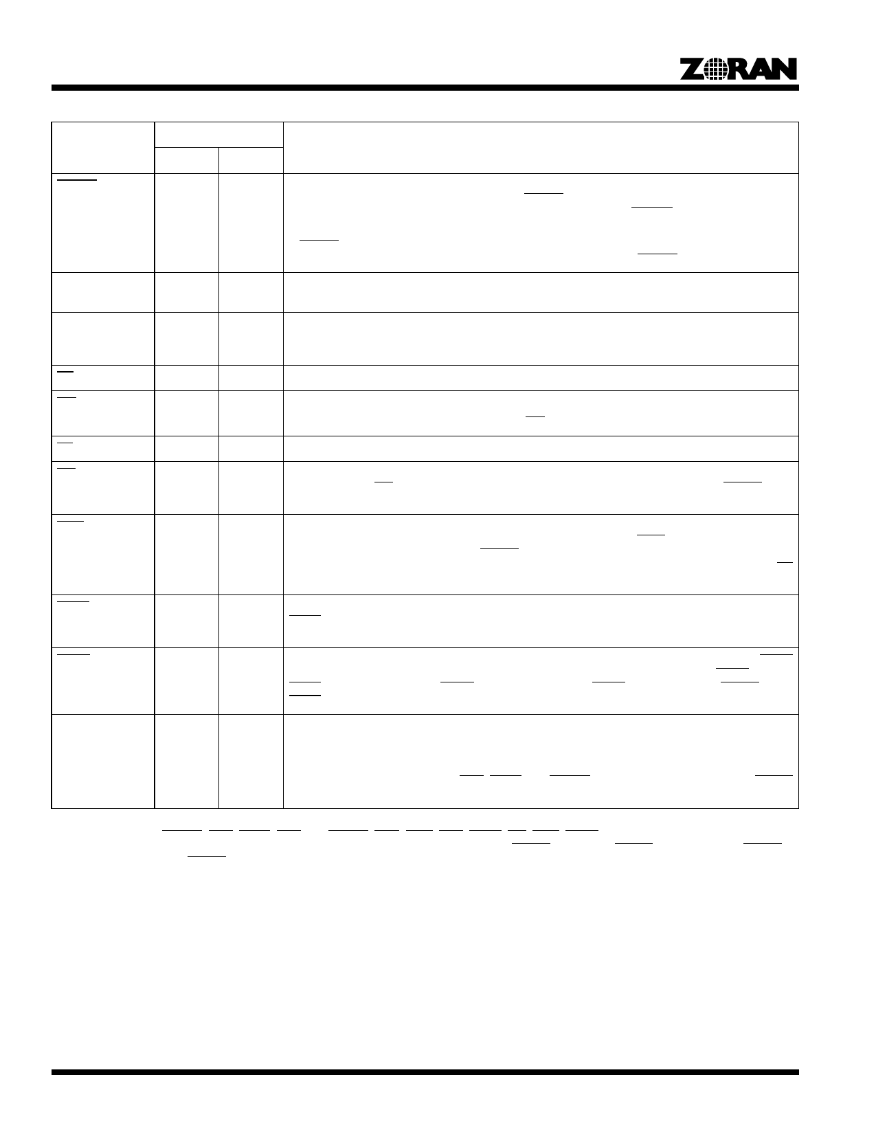
Table 1. Signal Description1, 2 (Continued)
Type3
Signal
Encode Decode
Description
CBUSY
I
I
Compressed Data Memory Busy. This active-low input signal indicates that the Compressed Data
Memory is busy. During the encoding modes, CBUSY active means that the ZR36050 cannot write
to the Compressed Data Memory. During the decoding modes, CBUSY active means that the
ZR36050 cannot read from the Compressed Data Memory.
If CBUSY is activated at least one CLK_IN prior to the beginning of a read or write cycle, then the
next read or write cycle will not be performed. The minimum width of CBUSY is one CLK_IN cycle.
ADDR(9-0)
I
I
Internal Memory Address. This 10-bit input bus is used to address the Internal Memory of the
ZR36050.
DATA(7-0)
B
B
Internal Memory Data Bus. This 8-bit bidirectional bus is used to read from or write to the Internal
Memory of the ZR36050. In the 16-bit Slave and DMA modes, the CODE bus is used as an extension
of the DATA bus.
RD
I
I
Read. This active-low input signal acts as a read pulse from the host to the ZR36050.
WR
I
I
Write. This active-low input signal acts as a write pulse from the host to the ZR36050.
The DATA bus is latched on the rising edge of WR.
CS
I
I
Chip Select. This active-low input signal acts as a chip select signal from the host to the ZR36050.
INT
O
O
Interrupt. This active-low output signal notifies the host that one of the STATUS bits, except for
DATRDY, is set. INT is reset by reading the relevant STATUS register, by activation of RESET, or by
a GO command.
DINT
O
O
Data Ready Interrupt. In Slave mode Compressed Data Transfer, this active-low output signal notifies
the host that the DATRDY bit in the STATUS_1 register is set. DINT is reset by reading the
STATUS_1 register, by activation of RESET, or by reading or writing the compressed data in the
Compressed Data Input/Output register at address 30H of the ZR36050 Internal Memory with CS
active.
DACK
I
I
DMA Acknowledge. This active-low input signal is used in DMA mode Compressed Data Transfer.
DACK is an acknowledgment pulse from the DMA controller to the ZR36050. It must be active during
the entire Read or Write cycle.
DREQ
O
O
DMA Request. This active-low output signal is used in DMA mode Compressed Data Transfer. DREQ
is the DMA request from the ZR36050 to the host. The ZR36050 does not output a DREQ until the
DACK signal to the previous DREQ has been deactivated.DREQ is deactivated by RESET, or by
DACK.
COMP
O
O
Compress/Expand. This output signal provides an indication of the current operating mode of the
ZR36050. When it is high, the ZR36050 is in the encoding mode; when it is low, the ZR36050 is in
the decoding mode. The mode and the state of COMP are changed when the MODE register in the
Internal Memory is read by the ZR36050 after a GO command is issued by the host. One CLK_IN
cycle after COMP changes state, EOS, STOP, and DSYNC change directions. Activation of RESET
sets COMP high.
1. The DATA, CODE, PIXEL, and COEF buses have internal pull-downs that provide 50 microamps of pull-down current at 0.4 volts.
2. The control pins: DSYNC, EOS, STOP, END, CL, CSYNC, COE, CWE, CCS, CAEN, INT, DINT, DREQ and COMP, have internal pull-up
devices that provide 50 microamps at 2.4 volts. These pull-ups are turned on only when STDBY is active but RESET is inactive. When STDBY
is active together with RESET, the above control pins float.
3. I = Input, O = Output, B = Bidirectional, S = Supply.
6
Share Link: 