ZR36050 Просмотр технического описания (PDF) - Zoran Corporation
Номер в каталоге
Компоненты Описание
Список матч
ZR36050 Datasheet PDF : 52 Pages
| |||
ADVANCE INFORMATION
ZR36050
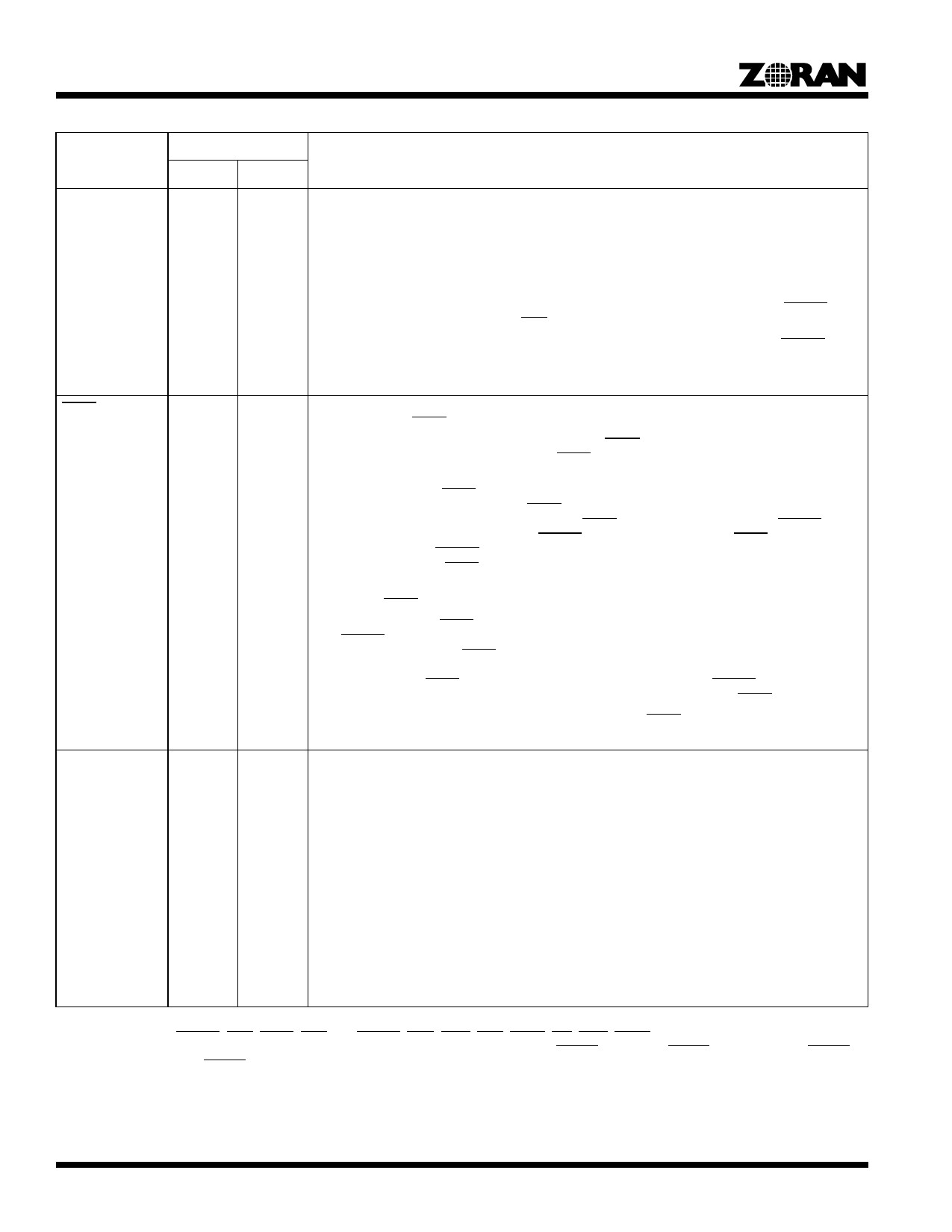
Table 1. Signal Description1, 2 (Continued)
Type3
Signal
Encode Decode
Description
CL(1-0)
-
O
Color. During the decoding mode, the CL output signals designate the index of the color component
that is being decoded.
00 - First MCU component.
01 - Second MCU component.
10 - Third MCU component.
11 - Fourth MCU component or Idle.
In the JPEG Baseline mode, the designation changes with the falling edge of the first DSYNC of the
component or with the falling edge of EOS.
In the Fast Preview and Lossless decoding modes, CL is active together with the DSYNC which
precedes the DC coefficient value and the pixel data, respectively.
CL is undefined in the encoding mode.
STOP
O
I
Stop Sending/Receiving. This active-low bidirectional signal is an input in encoding and output in
decoding modes. STOP is used for the following purposes:
At the start of and during an encoding operation, STOP is an output signal indicating that the
ZR36050 is not ready to receive image data. STOP is activated when the ZR36050 is in the Idle state,
and when reading or processing Internal Memory parameters during the encoding modes.
In the encoding mode, STOP is an output signal indicating that three of the ZR36050’s four internal
coefficient buffers are full. In this case, STOP is output 42 CLK_IN cycles prior to the last image data
sample of the current block that is being input. If STOP remains active until the next DSYNC is due,
then the system must not input the next DSYNC and the image data block. STOPs that are deacti-
vated prior to the next DSYNC can be ignored. The system can resume inputting the next image data
block immediately after STOP is deactivated.
In the Lossless encoding mode, the system must stop inputting data within three CLK_IN cycles of
activation of STOP to prevent overflow.
In the decoding mode, STOP is an input signal that notifies the ZR36050 that it should not assert the
next DSYNC and consequently delay output of the next decoded image data block at the end of the
current block. In this case, STOP must be activated at least 24 CLK_IN cycles before the last image
sample of the current block that is being output and must remain active at least until the end of the
current block. Once STOP is deactivated, the ZR36050 outputs the next DSYNC followed by its cor-
responding image data block, at least 17 CLK_IN cycles after deactivation of STOP.
In the Lossless decoding and Fast Preview modes, when STOP is activated or deactivated, the
ZR36050 stops or resumes delivering image data after 2 CLK_IN cycles.
PIXEL(11-0)
I
O
Pixel bus. This 12-bit unsigned bidirectional bus is used for the following purposes:
In the encoding modes, the most significant 8 bits are used to carry the input image data. The remain-
ing 4 bits are “don’t care” and can be left as unconnected pins.
In the Lossless encoding mode, it is a 12-bit input bus. If fewer than 12 bits are required, then the
most significant bits of the bus are used to carry the input image data.
In the decoding mode, the most significant 8 bits are used to carry the output image data. The least
significant 4 bits are forced to “0”.
In the Lossless decoding mode, this is a 12-bit output bus. If fewer than 12 bits are used, then the
most significant bits of the bus are used to carry the output image data and the unused bits are forced
to “0”.
In the Fast Preview mode, it is an output bus carrying the 11-bit unsigned DC coefficient values on
the most significant 11 bits of the bus. The least significant bit is forced to “0”.
The input/output data in the encoding and decoding modes is ordered in row-by-row scanned 8x8
blocks. In the Lossless encoding and decoding modes, the image data is scanned row by row.
1. The DATA, CODE, PIXEL, and COEF buses have internal pull-downs that provide 50 microamps of pull-down current at 0.4 volts.
2. The control pins: DSYNC, EOS, STOP, END, CL, CSYNC, COE, CWE, CCS, CAEN, INT, DINT, DREQ and COMP, have internal pull-up
devices that provide 50 microamps at 2.4 volts. These pull-ups are turned on only when STDBY is active but RESET is inactive. When STDBY
is active together with RESET, the above control pins float.
3. I = Input, O = Output, B = Bidirectional, S = Supply.
4
Share Link: 