DS1075 Просмотр технического описания (PDF) - Dallas Semiconductor -> Maxim Integrated
Номер в каталоге
Компоненты Описание
Список матч
DS1075 Datasheet PDF : 18 Pages
| |||
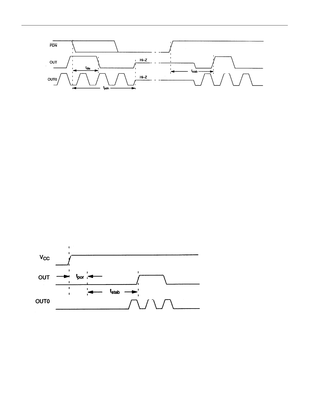
Figure 9
DS1075
POWER-ON RESET
When power is initially applied to the device supply pin, a power-on reset sequence is executed, similar
to that which occurs when the device is restored from a power-down condition. This sequence comprises
two stages, first a conventional POR to initialize all on-chip circuitry, followed by a stabilization period
to allow the oscillator to reach a stable frequency before enabling the outputs:
1. Initialize internal circuitry.
2. Enable internal oscillator and/or OSCIN buffer.
3. Set M and N to maximum values.
4. Wait approximately 256 cycles of MCLK for the oscillator to stabilize.
5. Load M and N programmed values from EEPROM.
6. Enable OUT0 (assuming EN0=0).
7. Enable OUT.
Figure 10
PROGRAMMING
Normally when power is applied to the supply voltage pin the device will enter its normal operating mode
following the power-on reset sequence. However the device can be made to enter a programming mode if
a pull-up resistor is connected between IN/OUT and the supply voltage pin, prior to power-up. The
method used for programming is a variant of the 1-Wire™ protocol used on a number of Dallas
Semiconductor products.
10 of 18
Share Link: 