DS1075 Просмотр технического описания (PDF) - Dallas Semiconductor -> Maxim Integrated
Номер в каталоге
Компоненты Описание
Список матч
DS1075 Datasheet PDF : 18 Pages
| |||
DS1075
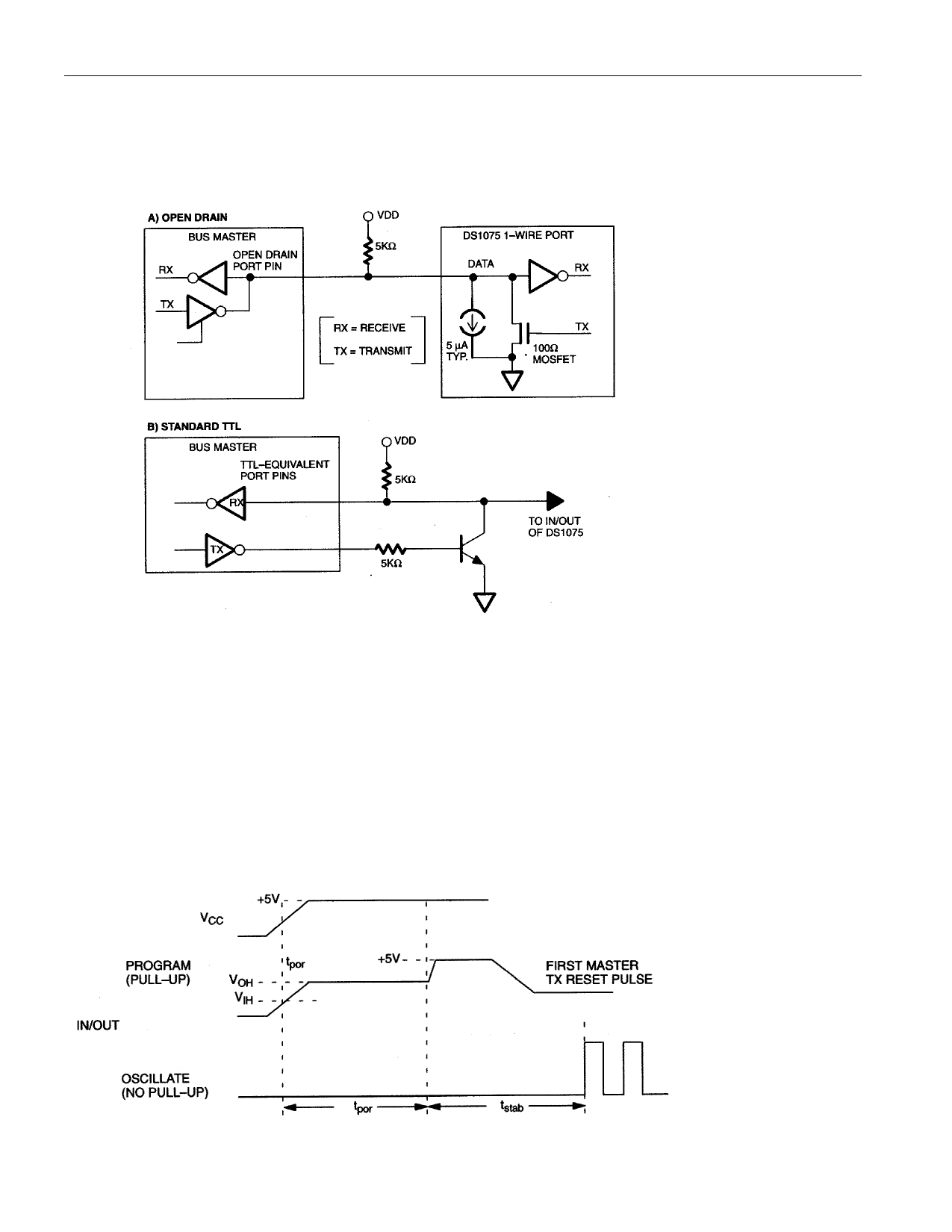
HARDWARE
The hardware configuration is shown in the diagram. A bus master is used to read and write data to the
DS1075’s internal registers. The bus master may have either an open-drain or TTL-type architecture.
Figure 11
Programming mode is entered by simply powering up the DS1075 with a pull-up of approximately 5KW.
This will pull the IN/OUT pin above VIH on power-up and initiate the programming mode, causing the
DS1075 to internally release the IN/OUT pin (after tPOR), and allow the pull-up resistor to pull the pin to
the supply rail and await the Master Tx Reset pulse (see diagram).
NOTE:
To ensure normal operation any external pull-up applied to IN/OUT must be greater than 20KW in value.
This will cause the IN/OUT pin to remain below VIH on power-up, resulting in normal operation at the
end of tSTAB.
Figure 12
11 of 18
Share Link: 