ZR36016 Просмотр технического описания (PDF) - Zoran Corporation
Номер в каталоге
Компоненты Описание
Список матч
ZR36016 Datasheet PDF : 36 Pages
| |||
Integrated Color Space / Raster-To-Block Converter
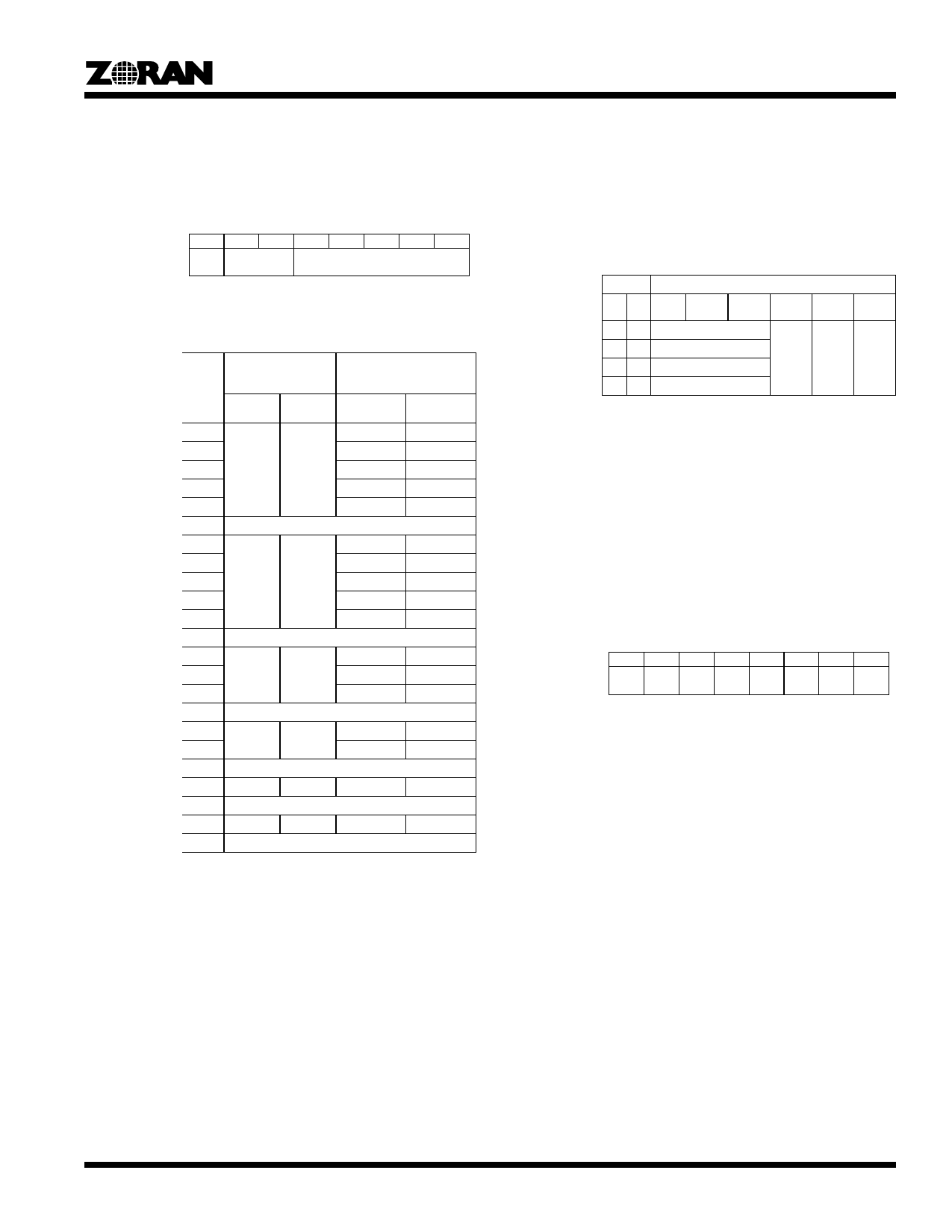
Mode Register
Read/Write
Initial Value
Function
Direct address: 0x01
0x91
Determines the basic operating modes and formats
of the ZR36016.
7
6
5
4
3
2
1
0
CMPR
DSPY
MODE
Bit 0-4 MODE: Determines the PXIN input and ZR36050
image formats and color spaces. Initial Value =
0x11.
PXBIN Bus
ZR36050 Image Format
Input (Compression)
Output (Expansion)
MODE
(HEX)
Image
Format
Color
Space
Image
Format
Color Space
00
4:4:4
RGB
4:4:4
YCbCr
01
4:2:2
YCbCr
02
03 [1]
4:1:1 (H2V2)
4:0:0
YCbCr
Y Only
04
4:4:4
RGB
05~07
Reserved
08
4:4:4
YCbCr
4:4:4
YCbCr
09
4:2:2
YCbCr
0A
0B [1]
4:1:1 (H2V2)
4:0:0
YCbCr
Y Only
0C
4:4:4
RGB
0D~10
Reserved
11
4:2:2
YCbCr
4:2:2
YCbCr
12
13 [1]
4:1:1 (H2V2)
4:0:0
YCbCr
Y Only
14, 15
Reserved
16
17 [1]
4:1:1
(PHILIPS)
YCbCr
4:1:1 (H4V1)
4:0:0
YCbCr
Y Only
18
Reserved
19
4:4:4:4
–
4:4:4:4
–
1A
Reserved
1B
1:0:0
–
1:0:0
–
1C~1F
Reserved
1. For Compression Only. If programmed for expansion,
then MODE = 0x16 is assumed.
2. RGB becomes YeMaCy when selected by the YMCS
bit in Setup Register 2.
3. MODE = 0x16 and 0x17 are the Philips 4:1:1 format.
Input and output pixel data use the upper 12 bits of
PXIN and PXOUT buses.
4. 4:1:1(H4V1) refers to a format in which the Cb and Cr
are decimated by 4 horizontally. 4:1:1(H2V2) refers to
a format in which the Cb and Cr are decimated by 2
horizontally and 2 vertically (sometimes known as
4:2:0 format).
5. The image format conversions implied by this table
are performed by Format Converter #1 in the block
diagram.
Mode Register (Continued)
Bits 5-6 DSPY: Determines the PXOUT bus output formats.
Initial Value = 0x00.
Setting this field of the Mode register selects the
output data format of the PXOUT bus, for each
format of the PXIN bus as selected by the MODE
field of the register, as shown in the table below.
DSPY
PXIN Bus Image Format [1]
Bit Bit 4:4:4
4:4:4
4:2:2
4:1:1
6 5 (RGB) (YCbCr) (YCbCr) (Philips)
1:0:0
4:4:4:4
0 0 PXOUT is 4:4:4 (RGB) PXOUT PXOUT PXOUT
is 4:1:1 is 1:0:0 is 4:4:4
0 1 PXOUT is 4:4:4 (YCbCr) (Philips)
1 0 PXOUT is 4:2:2 (YCbCr)
11
Reserved
1. The image format conversions implied by this table
are performed by Format Converter #2 in the block
diagram.
Bit 7 CMPR: Selects compression or expansion
Initial Value = 1
0 = Expansion Mode.
1 = Compression Mode.
Setup Register 1
Read/Write Indirect address: 0x00
Initial Value 0x01
7
6
5
4
3
2
1
0
CKRT VERT HORZ HRFL DSFL SBFL RSTR CNTI
Bit 0 CNTI: Single-Frame/Sequential processing
selection.
Initial value = 1.
0= Single Frame Mode. Processes the image enabled
by VIN and then enters an idle state. For process-
ing still images.
1= Sequential Mode. Processes sequential images in-
definitely, each VIN. For Motion JPEG.
Bit 1 RSTR: Transparent mode selection, for raster/
raster conversion.
Initial Value = 0.
0= Selects the raster-to-block or block-to-raster con-
version mode.
1= Selects the transparent raster-to-raster mode.
For the Fast Preview lossless compression/expan-
sion functions of the ZR36050. The image formats
supported, as set by the MODE field, are 4:4:4:4,
4:4:4, 4:2:2, or 4:1:1 (H4V1) (with pixel interleave).
As the ZR36050 performs 1-D lossless only, the
setting of RSTR = 1 in 4:1:1(H2V2) format is not
permitted.
Note: The strip buffer processing delay is the same
for both modes.
5
Share Link: 