ZR36016 Просмотр технического описания (PDF) - Zoran Corporation
Номер в каталоге
Компоненты Описание
Список матч
ZR36016 Datasheet PDF : 36 Pages
| |||
Integrated Color Space / Raster-To-Block Converter
Table 5: System Interface
Signal
I/O
Description
WINDOW
O Indicates data is within window area.
FBSY
O Frame busy. Indicates processing of frame.
START
I
Starts processing with the rising edge in single frame mode, or enables sequential mode.
SYSCLK
I
System clock. ZR36050 bus is synchronous with this clock.
PXCLK
RESET [1]
I
Pixel clock. HIN, VIN and PXIN are synchronous with this clock on input. HOUT, VOUT, PXOUT and WINDOW are
synchronous with this clock on output.
I
Initial hard reset. Must be held low for 8 SYSCLK cycles. Internal state remains reset for two sysclk cycles after
releasing RESET.
1. When RESET is active, HOUT, VOUT, CBSY, MWE and MOE are driven high, WINDOW, FBSY and MADD are driven low, PXOUT is unaffected (depends on PXIN
and PXOE as usual), DATA is unaffected (depends on CS and RD as usual), and BDATA, DSYNC, STOP, and EOS depend on COMP as usual.
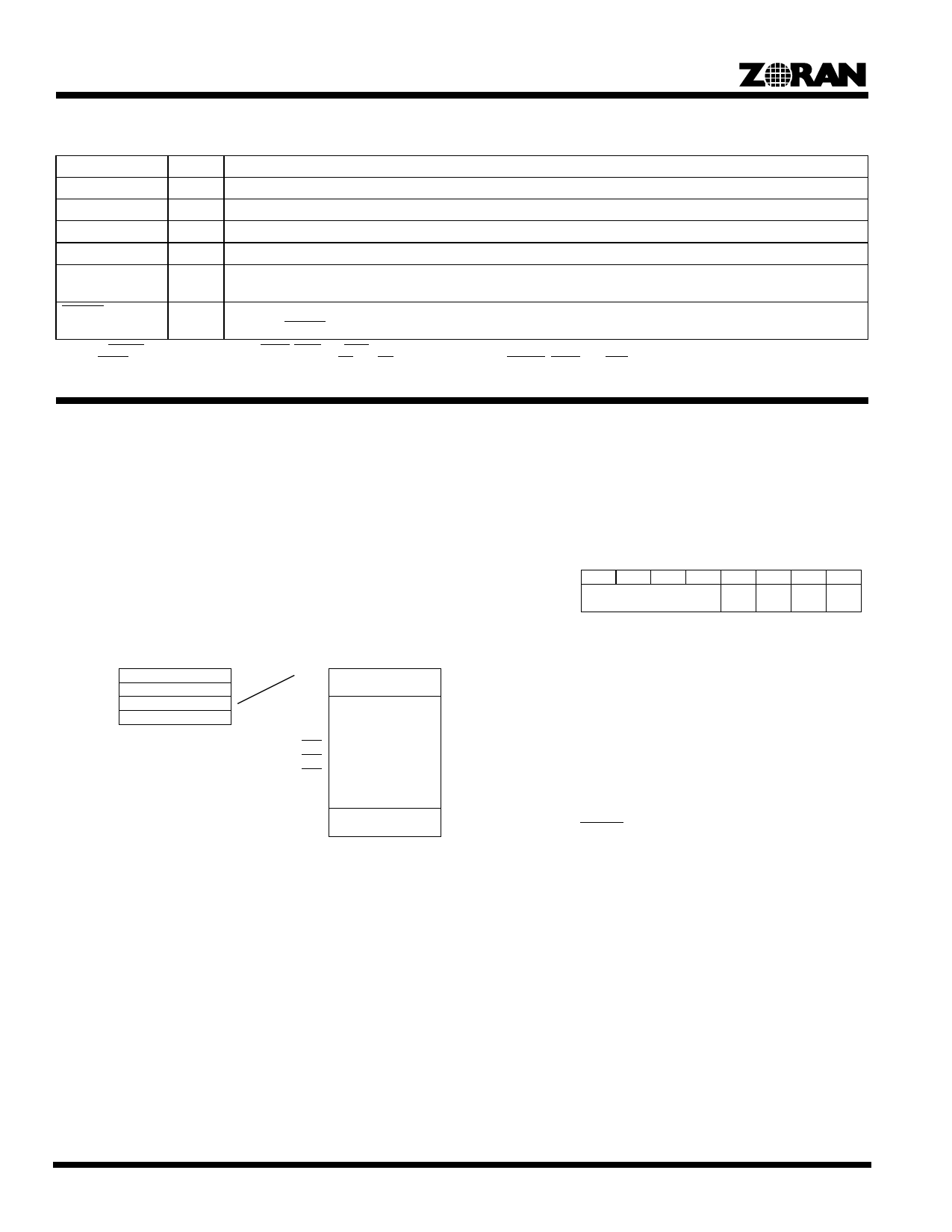
FUNCTIONAL DESCRIPTION
Control Registers
The internal control registers of the ZR36016 are shown in
Figure 3. The access to these registers is through the host inter-
face. Access to the Mode, Address Pointer and Configuration
Tables is possible only when the ZR36016 is idle or when FBSY
is not asserted. However, it is always possible to access the GO/
STOP register.
There are four byte-wide direct access registers and twelve
byte-wide indirect access registers.
ADD[1:0]
00
01
10
11
Direct Access Registers
GO/STOP
Mode
Address Pointer
Indirect Data
(Read/Write)
Address Pointer
0x00
0x01
0x02
0x03
0x04
0x05
0x06
0x07
0x08
0x09
0x0A
0x0B
Indirect Access Registers
Set Registers 1 & 2
(Read/Write)
Window Area Registers
(Read/Write)
Number of Lines Register
(Read Only)
Figure 3. Control Registers
Access to the indirect registers uses the Address Pointer direct
register. Its loaded value is used to point to the location from
which accesses start in the indirect registers. For example, to
write starting from the top of the Window Area Registers section,
write 0x02 in the Address Pointer register and after that write the
data in the Indirect Data register. After the first write to the
Address Pointer register, the address pointer is incremented
automatically after each access of the Indirect Data register. The
Address Pointer register stops incrementing at 0x0B, even if the
host continues to access the Indirect Data register.
GO/STOP Register
Read/Write
Initial Value
Function
Direct address: 0x00
0x00
Register to enable and stop processing by the
ZR36016.
7
6
5
4
3
2
1
0
Version Number
–
–
–
GO/
STOP
Bit 0 GO/STOP: Processing enable and stop bit.
Initial value = 0.
0= Terminates the processing.
1= Enables processing.
A 1 in the GO/STOP bit, in concert with the START
signal, enables processing by the ZR36016. Once
the GO/STOP bit has been set, processing will be
enabled when START is high. For compression the
actual processing period starts with the following
rising edge of VIN and for expansion with the first
DSYNC. Clearing the GO/STOP bit at any time
prevents the start of any future processing.
In the single frame mode the GO/STOP bit is
cleared automatically after the single frame has
been processed, and it must be set again to process
a new frame.
In the sequential mode, when GO is set it remains
set but the processing period can be controlled with
the START signal.
Bits 1-3 Reserved.
Bits 4-7 Version Number: The version number of the
ZR36016.
These bits contain the version number. Values start
at 0 and increment for each silicon step. Read only.
4
Share Link: 