8405202QA Просмотр технического описания (PDF) - Intersil
Номер в каталоге
Компоненты Описание
Список матч
8405202QA Datasheet PDF : 37 Pages
| |||
80C86
Absolute Maximum Ratings
Thermal Information
Supply Voltage . . . . . . . . . . . . . . . . . . . . . . . . . . . . . . . . . . . . . +8.0V
Input, Output or I/O Voltage . . . . . . . . . . . . GND -0.5V to VCC +0.5V
Gate Count. . . . . . . . . . . . . . . . . . . . . . . . . . . . . . . . . . . 9750 Gates
ESD Classification . . . . . . . . . . . . . . . . . . . . . . . . . . . . . . . . . Class 1
Operating Conditions
Operating Supply Voltage . . . . . . . . . . . . . . . . . . . . . +4.5V to +5.5V
M80C86-2 ONLY . . . . . . . . . . . . . . . . . . . . . . . . +4.75V to +5.25V
Temperature Range
C80C86-2 . . . . . . . . . . . . . . . . . . . . . . . . . . . . . . . . . 0°C to +70°C
M80C86-2. . . . . . . . . . . . . . . . . . . . . . . . . . . . . . .-55°C to +125°C
Thermal Resistance (Typical)
θJA (oC/W) θJC (oC/W)
PDIP Package* (Note 1) . . . . . . . . . . .
50
N/A
CERDIP Package (Notes 1, 2) . . . . . .
30
6
Storage Temperature Range . . . . . . . . . . . . . . . . -65°C to +150°C
Junction Temperature
Ceramic Packages . . . . . . . . . . . . . . . . . . . . . . . . . . . . . . +175°C
Plastic Packages . . . . . . . . . . . . . . . . . . . . . . . . . . . . . . . . +150°C
Pb-Free Reflow Profile . . . . . . . . . . . . . . . . . . . . . . . . see link below
http://www.intersil.com/pbfree/Pb-FreeReflow.asp
*Pb-free PDIPs can be used for through hole wave solder processing
only. They are not intended for use in Reflow solder processing
applications.
CAUTION: Do not operate at or near the maximum ratings listed for extended periods of time. Exposure to such conditions may adversely impact product reliability and
result in failures not covered by warranty.
NOTE:
1. θJA is measured in free air with the component mounted on a high effective thermal conductivity test board with “direct attach” features. See Tech
Brief TB379.
2. For θJC, the “case temp” location is the center of the exposed metal pad on the package underside.
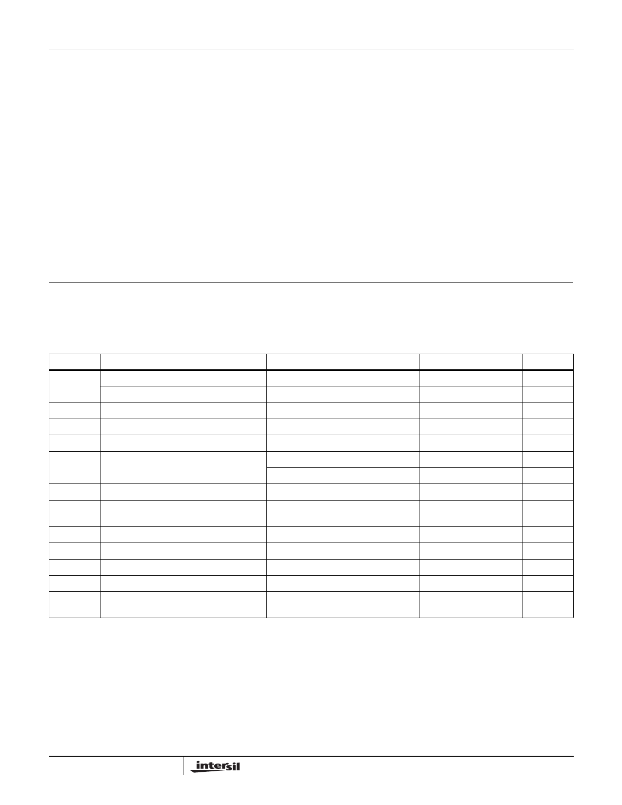
DC Electrical Specifications
VCC = 5.0V, ±10%; TA = 0°C to +70°C (C80C86, C80C86-2)
VCC = 5.0V, ±10%; TA = -55°C to +125°C (M80C86)
VCC = 5.0V, ±5%; TA = -55°C to +125°C (M80C86-2). Parameters with MIN and/or MAX limits are 100%
tested at +25°C, unless otherwise specified. Temperature limits established by characterization and are
not production tested.
SYMBOL
PARAMETER
TEST CONDITION
MIN
MAX
UNITS
VlH
Logical One
Input Voltage
C80C86 (Note 6)
M80C86 (Note 6)
2.0
V
2.2
V
VIL
VIHC
VILC
VOH
Logical Zero Input Voltage
CLK Logical One Input Voltage
CLK Logical Zero Input Voltage
Output High Voltage
VOL
Output Low Voltage
II
Input Leakage Current
lOH = -2.5mA
lOH = -100µA
lOL = +2.5mA
VIN = GND or VCC DIP
Pins 17-19, 21-23, 33
0.8
V
VCC - 0.8
V
0.8
V
3.0
V
VCC - 0.4
V
0.4
V
-1.0
1.0
µA
lBHH
lBHL
IO
ICCSB
ICCOP
Input Current-Bus Hold High
Input Current-Bus Hold Low
Output Leakage Current
Standby Power Supply Current
Operating Power Supply Current
VIN = - 3.0V (Note 3)
VIN = - 0.8V (Note 4)
VOUT = GND (Note 6)
VCC = - 5.5V (Note 5)
FREQ = Max, VIN = VCC or GND,
Outputs Open (Note 7)
-40
-400
µA
40
400
µA
-
-10.0
µA
-
500
µA
-
10
mA/MHz
17
FN2957.3
January 9, 2009
Share Link: 