AD73360AR Просмотр технического описания (PDF) - Analog Devices
Номер в каталоге
Компоненты Описание
Список матч
AD73360AR Datasheet PDF : 35 Pages
| |||
AD73360
FUNCTIONAL DESCRIPTION
General Description
The AD73360 is a six-channel, 16-bit, analog front end. It
comprises six independent encoder channels each featuring
signal conditioning, programmable gain amplifier, sigma-delta
A/D convertor and decimator sections. Each of these sections is
described in further detail below.
Encoder Channel
Each encoder channel consists of a signal conditioner, a
switched capacitor PGA and a sigma-delta analog-to-digital
converter (ADC). An on-board digital filter, which forms part
of the sigma-delta ADC, also performs critical system-level
filtering. Due to the high level of oversampling, the input
antialias requirements are reduced such that a simple single pole
RC stage is sufficient to give adequate attenuation in the band
of interest.
Signal Conditioner
Each analog channel has an independent signal conditioning
block. This allows the analog input to be configured by the user
depending on whether differential or single-ended mode is used.
Programmable Gain Amplifier
Each encoder section’s analog front end comprises a switched
capacitor PGA that also forms part of the sigma-delta modula-
tor. The SC sampling frequency is DMCLK/8. The PGA,
whose programmable gain settings are shown in Table IV, may
be used to increase the signal level applied to the ADC from low
output sources such as microphones, and can be used to avoid
placing external amplifiers in the circuit. The input signal level
to the sigma-delta modulator should not exceed the maximum
input voltage permitted.
The PGA gain is set by bits IGS0, IGS1 and IGS2 in control
Registers D, E and F.
Table IV. PGA Settings for the Encoder Channel
IxGS2
0
0
0
0
1
1
1
1
IxGS1
0
0
1
1
0
0
1
1
IxGS0
0
1
0
1
0
1
0
1
Gain (dB)
0
6
12
18
20
26
32
38
ADC
Each channel has its own ADC consisting of an analog sigma-
delta modulator and a digital antialiasing decimation filter. The
sigma-delta modulator noise-shapes the signal and produces
1-bit samples at a DMCLK/8 rate. This bitstream, representing
the analog input signal, is input to the antialiasing decimation
filter. The decimation filter reduces the sample rate and in-
creases the resolution.
Analog Sigma-Delta Modulator
The AD73360 input channels employ a sigma-delta conversion
technique, which provides a high resolution 16-bit output with
system filtering being implemented on-chip.
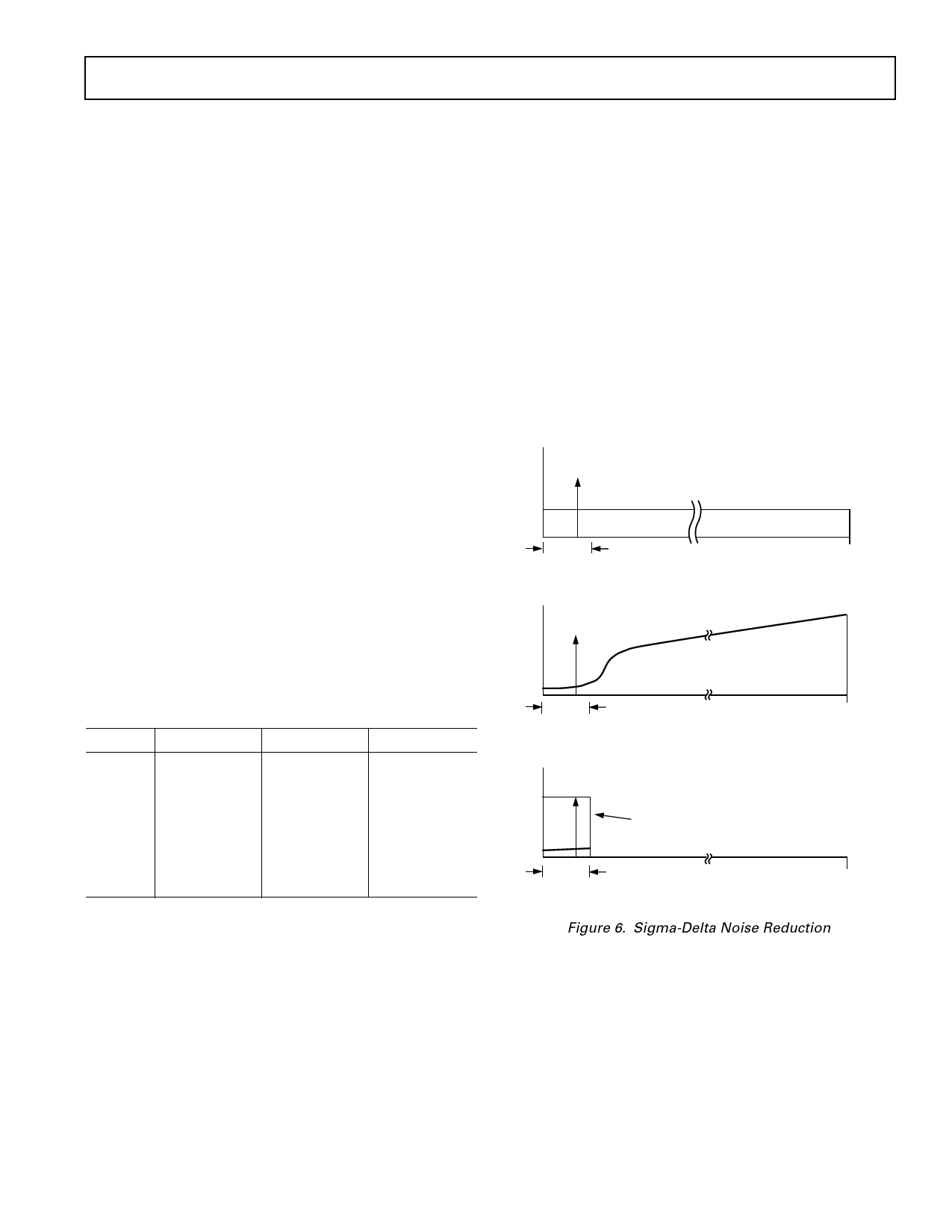
Sigma-delta converters employ a technique known as over-
sampling, where the sampling rate is many times the highest
frequency of interest. In the case of the AD73360, the initial
sampling rate of the sigma-delta modulator is DMCLK/8. The
main effect of oversampling is that the quantization noise is
spread over a very wide bandwidth, up to fS/2 = DMCLK/16
(Figure 6a). This means that the noise in the band of interest is
much reduced. Another complementary feature of sigma-delta
converters is the use of a technique called noise-shaping. This
technique has the effect of pushing the noise from the band of
interest to an out-of-band position (Figure 6b). The combina-
tion of these techniques, followed by the application of a digital
filter, reduces the noise in band sufficiently to ensure good
dynamic performance from the part (Figure 6c).
BAND
OF
INTEREST
a.
FS/2
DMCLK/16
NOISE-SHAPING
BAND
OF
INTEREST
b.
FS/2
DMCLK/16
DIGITAL FILTER
BAND
OF
INTEREST
c.
FS/2
DMCLK/16
Figure 6. Sigma-Delta Noise Reduction
REV. A
–11–
Share Link: 