ACT-D1M96S Просмотр технического описания (PDF) - Aeroflex Corporation
Номер в каталоге
Компоненты Описание
Список матч
ACT-D1M96S Datasheet PDF : 14 Pages
| |||
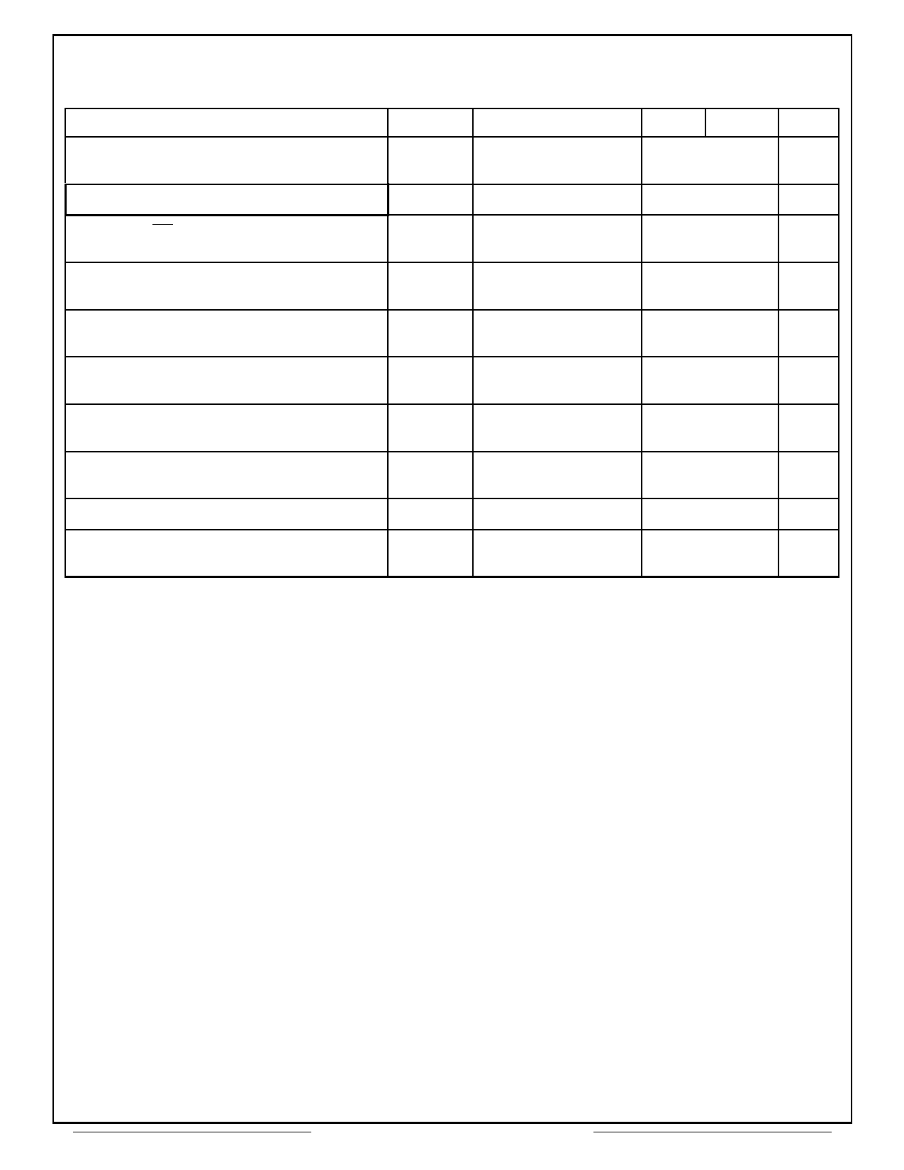
AC Timing†‡ (cont.)
(Vcc = 3.3V ±0.3V, Tc = -55°C to +110°C, See Note 4)
Parameter
Symbol
Test Conditions
Min
Max
Delay time, final data in of WRT operation to
DEAC or DCAB command
Refresh interval
tWR
tREF
20
50
Delay time, CS low or high to input enabled or
inhibited
nCDD
0
0
Delay time, CKE high or low to CLK enabled or
disabled
nCLE
1
1
Delay time, final data in of WRT operation to
READ, READ-P, WRT, or WRT-P
nCWL
1
Delay time, ENBL or MASK command to
enabled or masked data in
nDID
0
0
Delay time, ENBL or MASK command to
enabled or masked data out
nDOD
2
2
Delay time, DEAC or DCAB, command to DQ in
high-impedance state
Delay time, WRT command to first data in
nHZP2
nWCD
CAS latency = 2
2
0
0
Delay time, STOP command to READ or WRT
nBSD
2
command
† See Figure 2 - LVTTL Load Circuit for load circuits.
‡ All references are made to the rising transition of CLK, unless otherwise noted.
NOTES:
1. tAC is referenced from the rising transition of CLK that is previous to the data-out cycle. For example, the first data out tAC is
referenced from the rising transition of CLK within the following cycle: CAS latency minus one cycle after the READ command. An access time is measured
at output reference level 1.5 V.
2. For read or write operations with automatic deactivate, tRCD must be set to satisfy minimum tRAS .
3. CL = CAS Latency.
4. The temperature rise of θjc is negligible due to the low duty cycle during testing.
Units
ns
ms
cycle
cycle
cycle
cycle
cycle
cycle
cycle
cycle
Aeroflex Circuit Technology
10
SCD3369-1 REV C 5/31/00 Plainview NY (516) 694-6700
Share Link: 