CDP1854 Просмотр технического описания (PDF) - Intersil
Номер в каталоге
Компоненты Описание
Список матч
CDP1854 Datasheet PDF : 21 Pages
| |||
CDP1854A, CDP1854AC
CLEAR TO SEND (CTS):
When this input from peripheral is high, transfer of a
character to the Transmitter Shift Register and shifting of
serial data out is inhibited.
TRANSMITTER CLOCK (TCLOCK):
Clock input with a frequency 16 times the desired transmitter
shift rate.
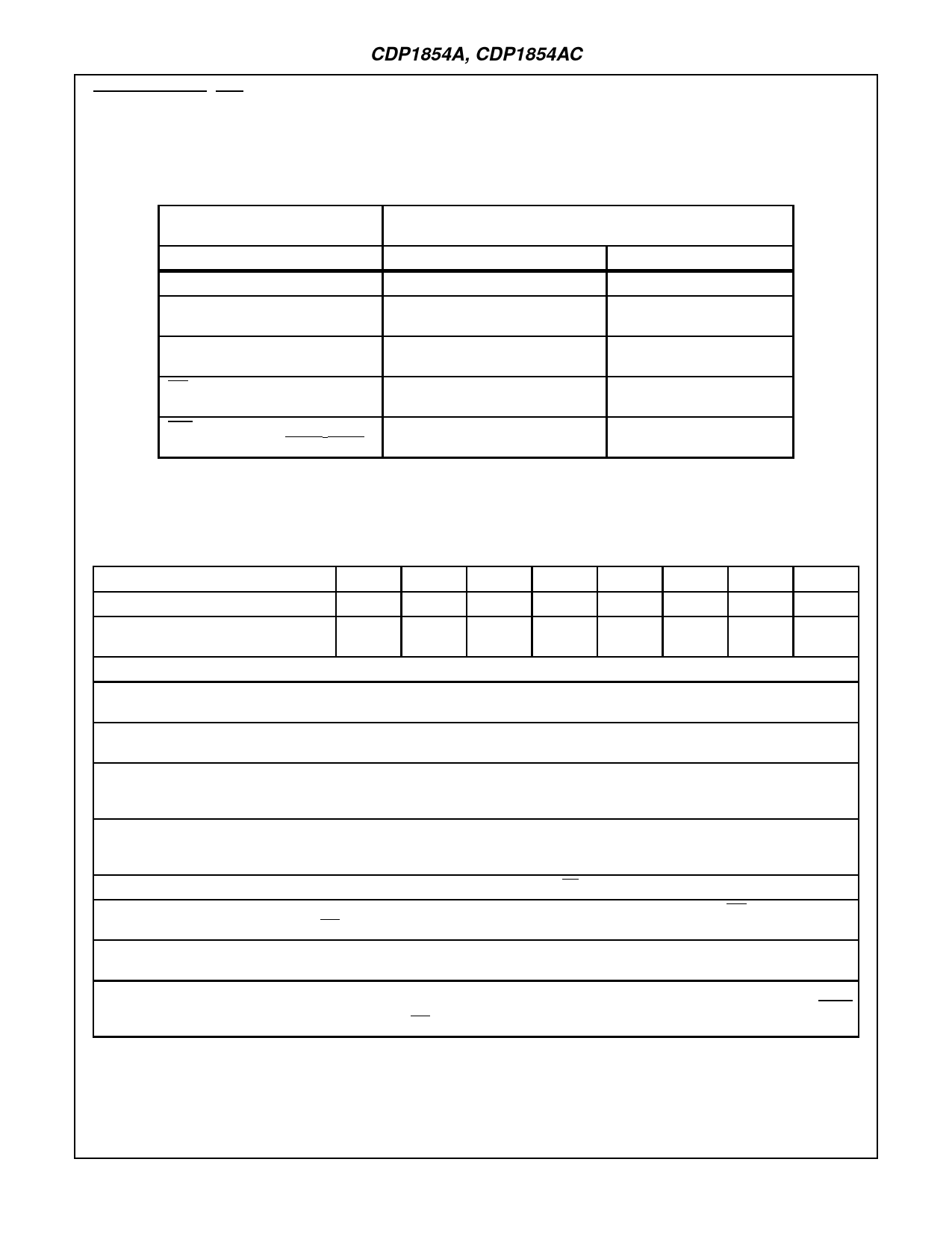
TABLE 1. INTERRUPT SET AND RESET CONDITIONS
(NOTE 1)
SET (INT = LOW)
RESET (INT = HIGH)
CAUSE
CONDITION
TIME
DA (Receipt of Data)
Read of Data
TPB Leading Edge
THRE (Note 2)
(Ability to Reload)
Read of Status or Write of Character TPB Leading Edge
THRE • TSRE
(Transmitter Done)
Read of Status or Write of Character TPB Leading Edge
PSI
(Negative Edge)
Read of Status
TPB Trailing Edge
CTS
Read of Status
(Positive Edge when THRE • TSRE)
TPB Leading Edge
NOTES:
1. Interrupts will occur only after the IE bit in the Control Register (see Table 4) has been set.
2. THRE will cause an interrupt only after the TR bit in the Control Register (see Table 4) has been set.
TABLE 2. STATUS REGISTER BIT ASSIGNMENT
BIT
7
6
5
4
3
2
1
0
SIGNAL
THRE TSRE
PSI
ES
FE
PE
OE
DA
ALSO AVAILABLE AT TERMINAL
22†
-
-
-
14
15
15
19†
† Polarity reversed at output terminal.
BIT SIGNAL: FUNCTION
0 DATA AVAILABLE (DA): When set high, this bit indicates that an entire character has been received and transferred to the Receiver
Holding Register. This signal is also available at Term. 19 but with its polarity reversed.
1 OVERRUN ERROR (OE): When set high, this bit indicates that the Data Available bit was not reset before the next character was
transferred to the Receiver Holding Register. This signal OR’ed with PE is output at Term. 15.
2 PARITY ERROR (PE): When set high, this bit indicates that the received parity bit does not compare to that programmed by the EVEN
PARITY ENABLE (EPE) control. This bit is updated each time a character is transferred to the Receiver Holding Register. This signal
OR’ed with OE is output at Term. 15.
3 FRAMlNG ERROR (FE): When set high, this bit indicates that the received character has no valid stop bit, i.e., the bit following the
parity bit (if programmed) is not a high-level voltage. This bit is updated each time a character is transferred to the Receiver Holding
Register. This signal is also available at Term. 14.
4 EXTERNAL STATUS (ES): This bit is set high by a low-level input at Term. 38 (ES).
5 PERIPHERAL STATUS INTERRUPT (PSI): This bit is set high by a high-to-low voltage transition of Term. 37 (PSI). The INTERRUPT
output (Term. 13) is also asserted (lNT = Iow) when this bit is set.
6 TRANSMlTTER SHIFT REGISTER EMPTY (TSRE): When set high, this bit indicates that the Transmitter Shift Register has complet-
ed serial transmission of a full character including stop bit(s). It remains set until the start of transmission of the next character.
7 TRANSMlTTER HOLDING REGISTER EMPTY (THRE): When set high, this bit indicates that the Transmitter Holding Register has
transferred its contents to the Transmitter Shift Register and may be reloaded with a new character. Setting this bit also sets the THRE
output (Term. 22) low and causes an INTERRUPT (lNT = low), if TR is high.
5-48
Share Link: 