RV5C386A_03 Просмотр технического описания (PDF) - RICOH Co.,Ltd.
Номер в каталоге
Компоненты Описание
Список матч
RV5C386A_03
RICOH Co.,Ltd.

RV5C386A_03 Datasheet PDF : 49 Pages
| |||
RV5C386A
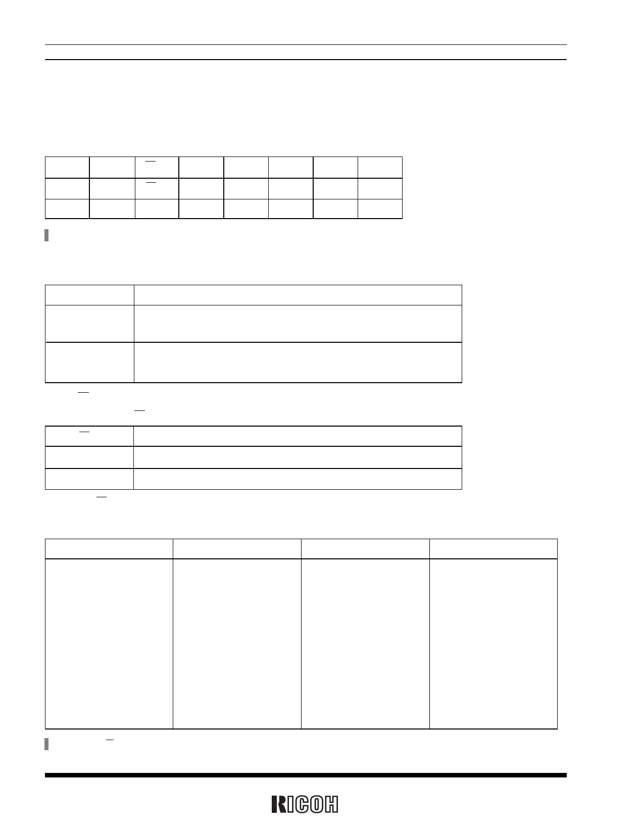
2. Register Settings
2.1 Control Register 1 (at Address Eh)
D7
D6
D5
D4
D3
D2
D1
D0
WALE DALE 12/24 SCRATCH3 TEST CT2
CT1
CT0 (For writing)
WALE DALE 12/24 SCRATCH3 TEST CT2
CT1
CT0 (For reading)
0
0
0
0
0
0
0
0
Default settings*1
*) Default settings: Default value means read/written values when the XSTP bit is set to “1” due to power-on from 0 volts or supply voltage drop.
2.1-1 WALE and DALE
Alarm_W Enable Bit and Alarm_D Enable Bit
WALE, DALE
0
Description
Disabling the alarm interrupt circuit (under the control of the settings of the
Alarm_W registers and the Alarm_D registers).
(Default setting)
Enabling the alarm interrupt circuit (under the control of the settings of the
1
Alarm_W registers and the Alarm_D registers)
2.1-2 12/24
12/24
0
1
12-/24-hour Mode Selection Bit
Description
Selecting the 12-hour mode with a.m. and p.m. indications.
Selecting the 24-hour mode
(Default setting)
Setting the 12/24 bit to 0 and 1 specifies the 12-hour mode and the 24-hour mode, respectively.
Table of Time Digit Indications
24-hour mode
12-hour mode
00
12 (AM12)
01
01 (AM 1)
02
02 (AM 2)
03
03 (AM 3)
04
04 (AM 4)
05
05 (AM 5)
06
06 (AM 6)
07
07 (AM 7)
08
08 (AM 8)
09
09 (AM 9)
10
10 (AM10)
11
11 (AM11)
24-hour mode
12
13
14
15
16
17
18
19
20
21
22
23
12-hour mode
32 (PM12)
21 (PM 1)
22 (PM 2)
23 (PM 3)
24 (PM 4)
25 (PM 5)
26 (PM 6)
27 (PM 7)
28 (PM 8)
29 (PM 9)
30 (PM10)
31 (PM11)
*) Setting the 12/24 bit should precede writing time data.
10
Share Link: