ZR36050 Просмотр технического описания (PDF) - Zoran Corporation
Номер в каталоге
Компоненты Описание
Список матч
ZR36050 Datasheet PDF : 52 Pages
| |||
ADVANCE INFORMATION
ZR36050
JPEG Lossless Encoding and Decoding
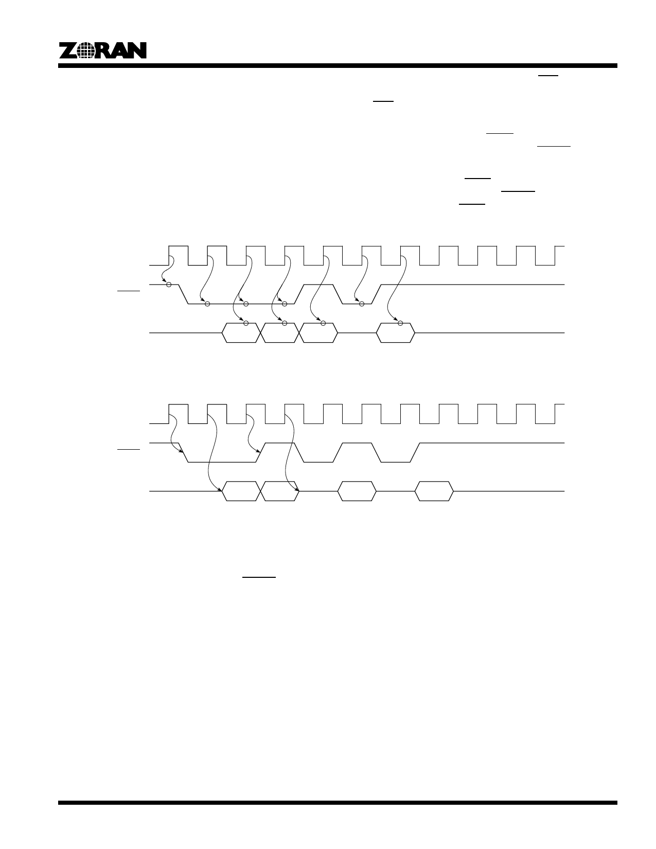
Figure 23 and Figure 24 show operation of the Pixel Interface in
JPEG Lossless encoding and decoding. The number of PIXEL
bus bits used depends on P, the sample precision parameter in
the JPEG frame header. If P specifies fewer than 12 bits, the
most significant P bits of the PIXEL bus are used. In decoding,
the Pixel Interface forces the unused bits to zero.
In encoding or decoding, a sample can follow the previous
sample immediately on the next clock, or the consecutive
samples can be separated by any number of clock cycles.
In encoding, the system logic must activate EOS together with
the last sample of the scan. In decoding, the Pixel Interface acti-
vates EOS within 64 CLK_IN cycles after the last sample of the
scan appears on the PIXEL bus.
If the Pixel Interface activates STOP during JPEG Lossless
encoding, the system logic must deactivate DSYNC to halt the
flow of data samples, within at most three CLK_IN cycles.
If the system logic activates STOP during JPEG Lossless decod-
ing, the Pixel Interface deactivates DSYNC one CLK_IN cycle
after it samples the active STOP.
CLK_IN
DSYNC
PIXEL
Figure 23. JPEG Lossless Encoding
CLK_IN
DSYNC
PIXEL
Figure 24. JPEG Lossless Decoding
DCT Coefficients Output
In JPEG Baseline encoding and decoding, the DCT coefficients
are output on the auxiliary COEF bus. The CSYNC synchroniz-
ing signal indicates the beginning of a block of coefficients. The
coefficients of a block are output in column order, starting with
the DC coefficient.
In encoding, the COEF bus outputs the DCT coefficients (before
quantization) of the block that was previously input on the PIXEL
bus, with a total delay of 81 CLK_IN cycles, as shown in
Figure 25. If, however, there is a break in the flow of data on the
PIXEL bus causing a gap between the last data sample of block
N and the first sample of block N+1, the same gap is reflected
into the COEF bus with a delay of 16 clock cycles. That is to say,
the gap appears between the last coefficient of the coefficient
block N-1 and the first coefficient of block N.
In decoding, the COEF bus outputs the DCT coefficients (after
dequantization) 80 CLK_IN cycles in advance of the next block
that will be output on the PIXEL bus, as shown in Figure 26. If,
however, there is a gap between the last coefficient of block N
and the first coefficient of block N+1, the same gap appears 16
clocks later on the PIXEL bus, between the last data sample of
block N-1 and the first sample of block N.
25
Share Link: 