VS-T110HF10 Просмотр технического описания (PDF) - Vishay Semiconductors
Номер в каталоге
Компоненты Описание
Список матч
VS-T110HF10 Datasheet PDF : 11 Pages
| |||
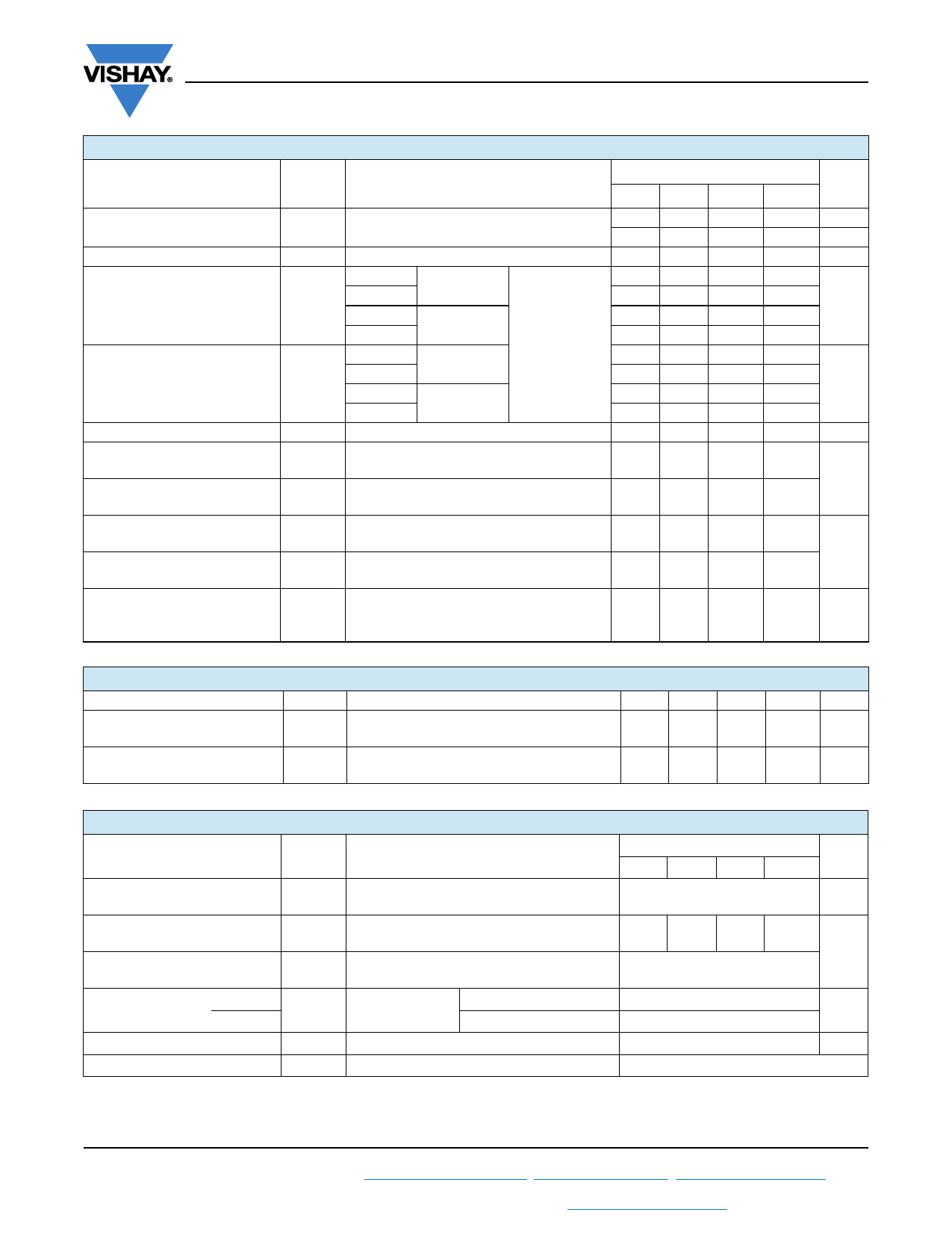
VS-T40HF..., VS-T70HF..., VS-T85HF..., VS-T110HF... Series
www.vishay.com
Vishay Semiconductors
FORWARD CONDUCTION
PARAMETER
SYMBOL
Maximum average forward
current at case temperature
Maximum RMS forward current
Maximum peak, one-cycle
forward, non-repetitive surge
current
IF(AV)
IF(RMS)
IFSM
Maximum I2t for fusing
I2t
Maximum I2t for fusing
Low level value of threshold
voltage
High level value of threshold
voltage
Low level value of forward slope
resistance
High level value of forward slope
resistance
I2t
VF(TO)1
VF(TO)2
rf1
rf2
Maximum forward voltage drop
VFM
TEST CONDITIONS
180° conduction, half sine wave
t = 10 ms No voltage
t = 8.3 ms reapplied
t = 10 ms
t = 8.3 ms
t = 10 ms
t = 8.3 ms
100 % VRRM
reapplied
No voltage
reapplied
Sinusoidal
half wave,
initial TJ =
TJ maximum
t = 10 ms 100 % VRRM
t = 8.3 ms reapplied
t = 0.1 ms to 10 ms, no voltage reapplied
(16.7 % x x IF(AV) < I < x IF(AV)),
TJ maximum
(I > x IF(AV)), TJ maximum
VALUES
UNITS
T40HF T70HF T85HF T110HF
40
70
85
110
A
85
85
85
85
°C
63 110 134
173
A
570 1200 1700 2000
600 1250 1800 2100
A
480 1000 1450 1700
500 1050 1500 1780
1630 7100 14 500 20 500
1500 6450 13 500 18 600
A2s
1150 5000 10 500 14 500
1050 4570 9600 13 200
16 300 70 700 148 700 204 300 A2s
0.66 0.76 0.68 0.68
V
0.84 0.95 0.90 0.86
(16.7 % x x IF(AV) < I < x IF(AV)),
TJ maximum
(I > x IF(AV)), TJ maximum
4.3 2.4 1.76 1.56
m
3.1 1.7 1.08 1.12
IFM = x IF(AV), TJ = 25 °C,
tp = 400 μs square pulse
1.30 1.35 1.27 1.35
V
Average power = VF(TO) x IF(AV) + rf x (IF(RMS))2
BLOCKING
PARAMETER
Maximum peak reverse
leakage current
RMS isolation voltage
SYMBOL
TEST CONDITIONS
IRRM
VISOL
TJ = 150 °C
50 Hz, circuit to base, all terminals shorted
TJ = 25 °C, t = 1 s
T40HF T70HF T85HF T110HF UNITS
15
15
20
20
mA
3500 3500 3500 3500
V
THERMAL AND MECHANICAL SPECIFICATIONS
PARAMETER
SYMBOL
TEST CONDITIONS
VALUES
UNITS
T40HF T70HF T85HF T110HF
Maximum junction operating
and storage temperature range
TJ, TStg
-40 to +150
°C
Maximum thermal resistance,
junction to case per junction
Maximum thermal resistance,
case to heatsink
RthJC
RthCS
DC operation
Mounting surface smooth, flat
and greased
1.36 0.69 0.62 0.47
K/W
0.2
Mounting torque, to heatsink
Non-lubricated M3.5 mounting screws (1)
1.3 ± 10 %
Nm
± 10 %
terminals
threads
M5 screw terminals
3 ± 10 %
Approximate weight
See dimensions - link at the end of datasheet
54
g
Case style
D-55 (T-module)
Note
(1) A mounting compound is recommended and the torque should be rechecked after a period of about 3 hours to allow for the spread of the
compound
Revision: 20-Dec-16
2
Document Number: 93587
For technical questions within your region: DiodesAmericas@vishay.com, DiodesAsia@vishay.com, DiodesEurope@vishay.com
THIS DOCUMENT IS SUBJECT TO CHANGE WITHOUT NOTICE. THE PRODUCTS DESCRIBED HEREIN AND THIS DOCUMENT
ARE SUBJECT TO SPECIFIC DISCLAIMERS, SET FORTH AT www.vishay.com/doc?91000
Share Link: 