GF9101-CMQ Просмотр технического описания (PDF) - Gennum -> Semtech
Номер в каталоге
Компоненты Описание
Список матч
GF9101-CMQ Datasheet PDF : 23 Pages
| |||
FILTER ARCHITECTURE
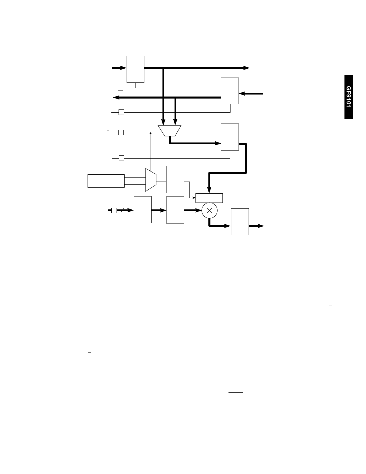
For the following discussion on filter architecture, refer to the GF9101 Block Diagram and Figure 4.
+10.0
DATA _A_IN
+10.0
A REG
TO NEXT TAP
ENA
R
TO NEXT
TAP
ENB
R
B REG
+10.0
+10.0
DATA_B_IN
SEL–A/B
R
10
+10.0
C REG
ENC
R
MODE A 0
CONFIGURATION
REGISTER
MODE B 1
MULT
MODE
REG
SIGNED /
UNSIGNED
+10.0
7
COEF–ADDR R
108 x12
COEF
±0.11
REG
COEF
REG
+10.0 / ±9.0
±0.11
±10.11
MULT ±10.11
REG
TO ADDER
Fig. 4 Tap Cell (1-12)
COEFFICIENT MULTIPLICATION AND ADDITION STAGE
Two shift registers, A and B, are used to shift input data
through the GF9101. Notice that if DATA_B_SEL was set low
during configuration, data applied at DATA_A_IN enters at
tap 1 and exits from tap 12, while data applied at
DATA_B_IN enters at tap 12 and exits from tap 1. This gives
two 12 tap filters. If DATA_B_SEL was set high during
configuration, data applied at DATA_A_IN enters at tap 1,
reverses direction at tap 12 (bypasses REG_12B) and exits
from tap 1 on DATA_B_OUT, while DATA_B_IN is disabled.
This gives a 23 tap filter. ENA and ENB control the shifting
of the input data. The C register holds the next set of 12
input values to be applied to the multipliers.
If ENC is high, SEL_A/B, determines whether the A or B shift
register data enters the C register. SEL_A/B, also
determines whether the MODE A or MODE B control signal
enters the MULT_MODE register. The value in the
MULT_MODE register determineswhether theinputdatato
themultiplierisrecognized as signed or unsigned. MODE A
and MODE B are separate, static control signals which
determine signed/unsigned for A or B input data
respectively. They are common to all taps. When using the
GF9101 as a 23 or 24 tap filter (combiningREG_A and
REG_B to get a single filter output), MODE A and MODE B
should be in the same state. If not, a signed/unsigned
mismatch will occur. One needs to be cautious while using
the GF9101 as two separate filters with MODE A and MODE
B not in the same state (data entering REG_A is signed/
unsigned while in REG_B it is the opposite of REG_A) . If
ENC is low and SEL_A/B, changes state, a signed/unsigned
mismatch will occur. To avoid an error under these
circumstances, always make ENC high after a SEL_A/B,
state change.
The input values in the C register are multiplied by the
coefficient values in the COEF register and the result enters
an adder tree . The coefficients that enter the COEF register
are stored in the internal RAM and are selected by the
externally controlled COEF_ADDR (6-0) bus, which is
common to all taps. At the output of the adder tree is the
untruncated sum of taps 1 through 12.
This sum is then truncated as shown in the GF9101 Block
diagram. The sum then passes through a variable delay
along with the ZERO and NEGATE signals. The variable
delay is provided so that complementary sums from
cascaded GF9101’s may be added together in the
pipelined output stage. The ZERO signal zeros the sum and
the NEGATE signal negates the sum.
7
520 - 64 - 7
Share Link: 