GF9101 Просмотр технического описания (PDF) - Gennum -> Semtech
Номер в каталоге
Компоненты Описание
Список матч
GF9101 Datasheet PDF : 23 Pages
| |||
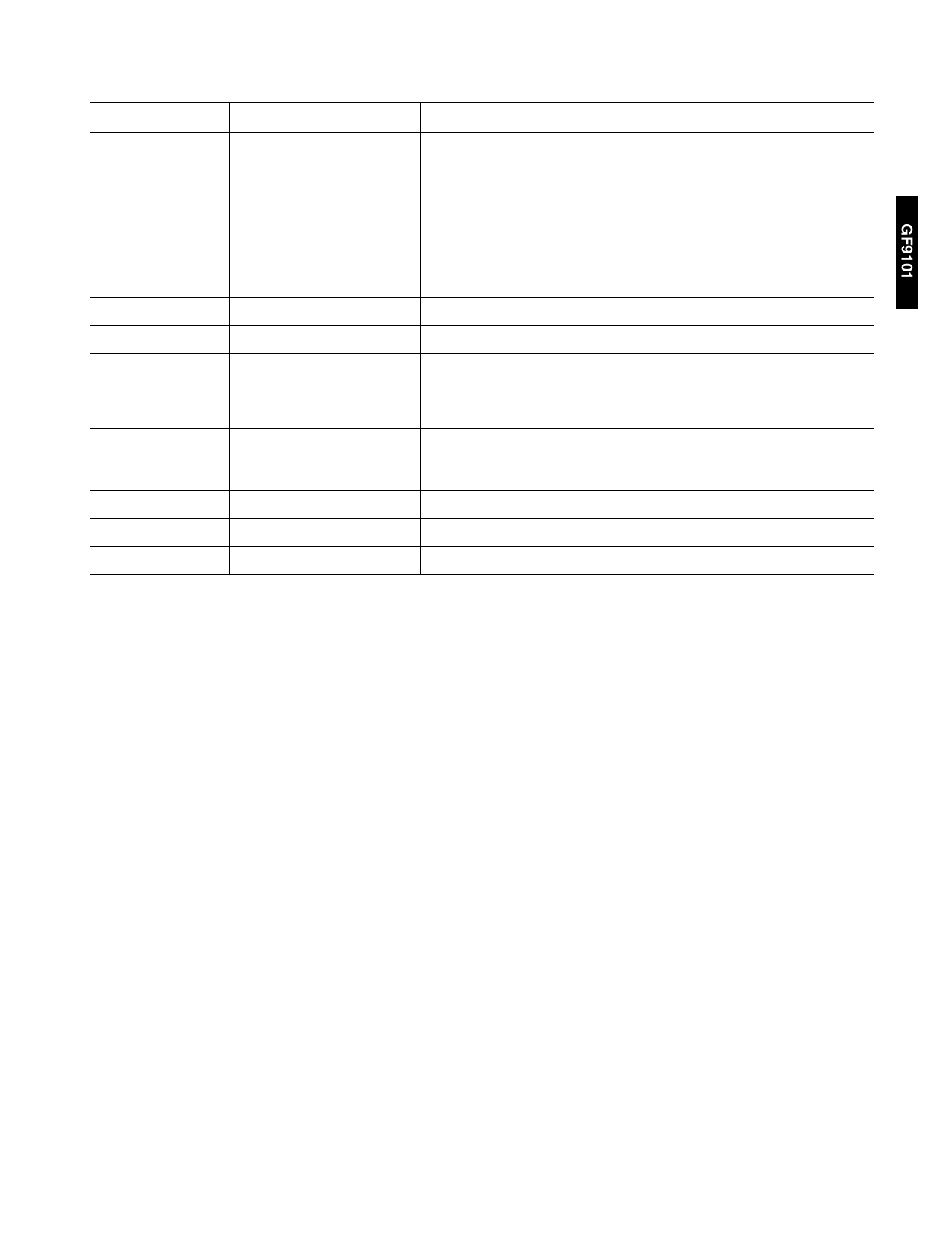
I/O DESCRIPTION
SYMBOL
PIN NO.
TYPE
DESCRIPTION
CONFIGURE
21
I
GF9101 reset/configure. Resets the GF9101 when high for at least one clock
period. Loads COEF_DATA (6-0) into the CONFIGURATION register on a high
to low transition. This bit is set low in run mode. When CONFIGURE is high,
the GF9101 is reset but the values in the internal RAM and registers in the run
mode sections are not altered. This means that the GF9101 may be
reconfigured after the internal RAM has been loaded.
PIPELINE_IN (19-0)
38,37, 35, 34, 32-30,
28-26, 15-11, 9, 7, 5,
4, 2
I
Pipeline input. Input to the output accumulator when FB_SEL is low.
DATA_A_OUT (9-0)
71, 70, 68-61
O Output data from register A11.
DATA_B_OUT (9-0)
58-50, 48
O Output data from register B0.
PIPELINE_OUT (19- 82, 84, 85, 87, 89, 91- O Pipeline output. Output of the accumulator or PIPELINE_IN depending on
0)
95, 106-108, 110-
FB_SEL.
112, 114, 115, 117,
118
S_LOAD_CMP
16
O Serial loading complete.
a) Serial loading mode: When high, indicates that all the internal RAM has
been loaded.
SCAN_IN, SCAN_EN
157, 156
Set low.
TEST
158
Set high.
POUT, SCANOUT
152, 154
No Connect.
Note: All unused inputs of the GF9101 should be connected to GND
GF9101 OPERATION
The GF9101 has two operating modes: the load mode and
the run mode. In the load mode, the coefficients for the
filters are written to the internal RAM. In the run mode, the
GF9101 is used to filter signals.
Before the GF9101 can filter signals, two steps must be
performed:
1. CONFIGURATION - is accomplished by writing one 7 bit
word into the CONFIGURATION REGISTER. This register
holds static operating parameters that affect both the
load mode and the run mode.
2. MEMORY LOADING - is done after configuration. The
internal RAM must be loaded with at least one of the 108
filter coefficient sets before signals can be processed.
CONFIGURATION
The GF9101 is reset by holding CONFIGURE high for at
least one clock cycle. Configuration occurs upon a high to
low transition on the CONFIGURE pin. This transition
registers COEF_DATA (6-0) into the CONFIGURATION
REGISTER. Table 1 shows the meaning of each bit in the
CONFIGURATION REGISTER.
When CONFIGURE is high, the GF9101 is reset but the
values in the internal RAM and registers in the run mode
sections are not altered. This means that the GF9101 may
be reconfigured after the internal RAM has been loaded.
MEMORY LOADING
The GF9101 contains 12 tap cells with 108 12-bit memory
locations for each tap. When loading the memory, the tap
cells must be viewed as 6 memory banks with 108 24-bit
memory locations in each bank. Each memory bank is
assigned to a pair of tap cells as shown in Table 2.
During configuration, either the parallel, microprocessor, or
serial loading is selected. When in the load mode, the
memory outputs are undefined. Please refer to the GF9101
block diagram and notice that, even though the memory
outputs are undefined, several valid outputs may be in the
processing section below the multipliers and can exit the
GF9101 correctly. This would be useful for adaptive filtering
where the tap memories can be changed while the GF9101
outputs are still valid. During power up, the internal RAM of
the GF9101 is in a random state, and is not intialized to
zero.
3
520 - 64 - 7
Share Link: 