CS7654 Просмотр технического описания (PDF) - Cirrus Logic
Номер в каталоге
Компоненты Описание
Список матч
CS7654 Datasheet PDF : 62 Pages
| |||
CS7654
Digital Output Formats
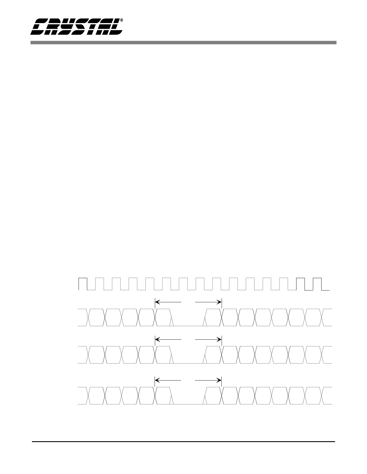
The CS7654 can output data in a 10-bit format at
a 2x output pixel clock rate. Figure 3 details the
clock and data relationships. The output data tran-
sitions on the falling edge of the clock such that the
rising edge of the clock can be used to latch the data
into subsequent circuitry.
The CS7654 delivers 4:2:2 component digital vid-
eo output data in YCrCb format. The data conforms
to the ITU-R BT.656 specification. The Y compo-
nent range is 16-235 (8-bit data) and the Cr and Cb
component ranges are 16-240 (8-bit data). Howev-
er, by setting CLIP_OFF (register 07h bit 6 at
SA34h) to a value of 1, the output data can be ex-
tended to a range of 1-254 (8-bit data). Only 00 and
FF are restricted to allow digital timing codes. The
CLIP_OFF register will set the digital section on
the data path to the extended range of value. If you
want to have the analog output set to extended
range, you will also have to set Register 06h at Sta-
tion Address (SA ) 0x00.
The digital outputs are configured for 10-bit inter-
leaved Y and CrCb data
The CS7654 supports both 8-bit and 10-bit opera-
tion as per the ITU-656 recommendation. The ITU-
656 recommendation defines the primary data path
as 8-bits wide with two additional fractional bits
that can be used to form a 10-bit data path. If only
8-bits of output data are used, the two LSBs,
DOUT1 and DOUT0 are not used. However,
DOUT[9:2] is connected exactly the same as in a
10-bit system. This is essential to properly pass the
image data and synchronization signals to the next
component.
Internal Horizontal Scaler
The internal horizontal scaler is used to bridge be-
tween common CCD imager formats and computer
or television formats.
Several pre-defined scaler modes may be selected
by writing a 3-bit value to bits 0-2 of register 04h at
SA 0x34h. These default scaling modes are de-
scribed in Table 2. If the CUSTOM bit (bit 3 of reg-
ister 04h at SA 0x34h) is set to a 1, then the scaling
ratio is determined by the M and N values con-
tained in the Scaler Control registers (2Dh - 2Fh at
SA 0x34h.)
24.5454MHz
CLKOUT
DOA[9-0]
Line 3 Pixel 776
to Line 4 Pixel 3
SAV
80h 10h 80h 10h FFh 00h 00h ABh 80h 10h 80h 10h 80h 10h
DOA[9-0]
Line 263 Pixel 638
to Line 264 Pixel 645
EAV
80h 10h 80h 10h FFh 00h 00h F1h 80h 10h 80h 10h 80h 10h
DOA[9-0]
Line 525 Pixel 638
to Line 1 Pixel 645
EAV
Cb638 Y638 Cr638 Y639 FFh 00h 00h 9Dh 80h 10h 80h 10h 80h 10h
NOTE: EAV, SAV, and Blanking data values are based on the 8 MSB’s of the output data, the two LSBs are considered fractional.
Figure 3. 2x Pixel Clock, 10-Bit interleaved Output Format for 640x480 Image Format.
11
Share Link: 