STV0502 Просмотр технического описания (PDF) - STMicroelectronics
Номер в каталоге
Компоненты Описание
Список матч
STV0502 Datasheet PDF : 15 Pages
| |||
STV0502
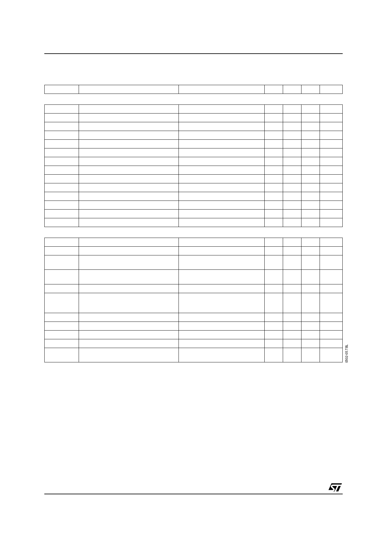
ELECTRICAL CHARACTERISTICS
Tamb = 25oC, VDD = VCC = 5V, unless otherwise specified (continued)
Symbol
Parameter
Test Conditions
Min. Typ. Max. Unit
VIDEO CDS
RIN
CIN
INDyn
CDS_SR
CDS_DR
CDS_HM
CDS_lin
CDS Gain
ROUT
OUTload
FS
FCDS
PIX_FRE
PSRR
Input Resistance
Input Capacitance
Input Dynamic Range
S/H Slew Rate
S/H Droop Rate
S/H Hold Mode Feed through
CDS Linearity
Overall Input to Output Gain
CDS Output Impedance
CDS Ouput Load
PS Pulse Width
FSDS Pulse Width
Pixel Rate
Power Supply Rejection
Pin 4
Pin 4
Pin 4, before output clipping
Pin 2, FS high
Pin 2, FS low
Pin 2, FS low, fIN = 1MHz
Pin 2, 500mVPP (1)
Pin 2, normal operation
Pin 2, FCDS & FS high
See timings
See timings
Pins 4, 21, 22
Measured on Pin 2 (2)
8 11 14 kΩ
6
pF
0.6 0.7
VPP
0.6 0.9
V/15ns
-20
+20 mV/µs
-55 -45 dB
0.3 1.5 %
-2 -1 0
dB
250 Ω
100
Ω
12
ns
12
ns
6 12
MHz
60
dB
VIDEO AMPLIFIER
RIN
CIN
Min. Gain
Max. Gain
Min. Gain
Max. Gain
Gset-err
Out_Max
Input Resistance
Input Capacitance
Minimum Gain
Maximum Gain
Minimum Gain
Maximum Gain
Gain Setting Relative Error
Max. Output Signal before clipping
tR
tF
tPROP
PSRR
Xtalk
Output Rise Time
Output Fall Time
AGC Propagation Time
Power Supply Rejection
Xtalk from Video to Audio
Pin 1
2
kΩ
Serial bus from H00 to HFF
18
pF
Serial bus = H00/no extra gain
6 6.5 dB
Serial bus = HFF/no extra gain 23.2 23.7
dB
Serial bus = H00/extra gain
Serial bus = HFF/extra gain
12 12.5 dB
35.2 35.7
dB
Serial bus from H00 to HFF
-0.5
0.5 dB
Pin 38, VCC = 4.5V
G = 6dB, VIN = 0.8VPP
G = 23.7dB, VIN = 0.1VPP
1.6
VPP
1.6
VPP
Square input
10 15
ns
Square input
10 15
ns
Pin 1 to Pin 38
15 20
ns
Measured on Pin 38 (2)
45
dB
Measured on Pin 38, compared
60
dB
to Pins 20 and 21 (2)
Notes : 1. Normal operation means FS & FCDS run at specified timings and 12MHz frequency.
2. On a 20Hz to 10MHz frequency range, with 10µF filtering capacitors on all supplies, and well splitted supplies and grounds.
8/15
Share Link: 