QT300 Просмотр технического описания (PDF) - Quantum Research Group
Номер в каталоге
Компоненты Описание
Список матч
QT300 Datasheet PDF : 14 Pages
| |||
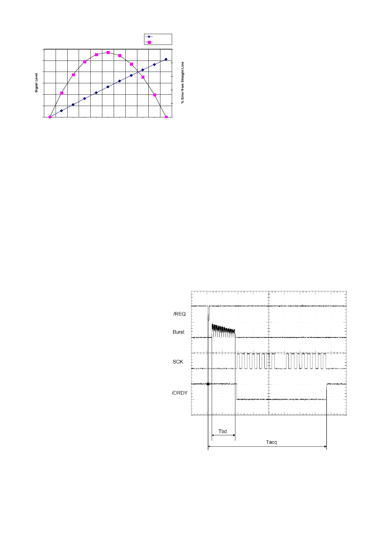
Figure 1-3 Linearity vs Cx, Over Cx= 100pF...110pF
300
Signal Level
% Error
3%
250
2%
200
2%
150
1%
100
1%
50
0
0%
100 101 102 103 104 105 106 107 108 109 110
Cx, pF
linearity decreases to under 3% (Figure 1-3). The largest
error occurs near the middle of the desired Cx span.
The linearity error can be corrected using polynomials or a
piece-wise linear correction method in a microcontroller.
2 - Timing
Figure 2-1 shows the basic QT300 acquisition timing
parameters. The basic timing parameters are:
Tbd Burst duration
(2.1)
Tacq Acquire response time (2.2)
Tbs Burst Spacing
(2.3)
2.1 Tbd - Burst duration
The burst duration depends on the values of Cs and Cx and
to a lesser extent, Vdd. The burst is composed of
charge-transfer cycles operating at about 240kHz.
The length of this burst is an important parameter as it is
directly related to the signal value. The burst duration also
affects the response time of the sensor; the
larger Cs is, the longer the burst, the slower the
possible acquisition rate.
or 1W pin. The QT300 only acquires when requested. While
waiting for a new request the part stays in a low power mode.
3 - SPI Port
3.1 SPI Specifications
The QT300 can operate in master or slave mode, and thus is
compatible with virtually all SPI-capable microcontrollers. The
SPI interface has the following specifications:
Max clock rate, Fckm
Max clock rate, Fcks
Data length
Inter-byte delay
Clock idle logic level
Clock edge
Data sequence
40KHz (master mode)
40KHz (slave mode)
2 bytes (16 bits total)
≥8µs (master mode)*
≥12µs (slave mode)
Low or High*
Data out on rising or falling edge*
High byte first, MSB first
*Determined by Setups
The host can clock the SPI at any rate up to and including
the maximum. The maximum clock rate of the part in Master
mode is determined in Setups via cloning.
3.2 Protocol Overview
The QT300 only transmits data on request, after an
acquisition burst. The host requests an acquire by setting the
/REQ line low for at least 30µs; the device then acquires.
When finished, the DRDY line is pulled low by the QT300 to
indicate it is ready to send data. (Figure 2-1). The transfer is
done as two bytes, with the highest byte transferred first.
In master mode, /DRDY goes high between bytes for the
period determined by Setup parameter MLS; this is a multiple
of 6µs.
2.2 Tacq - Acquire Response Time
The time from the /REQ or 1W line going low
until the completion of data transmission is
Tacq. Tacq depends on the acquisition burst
length as well as the serial transmission time.
SPI Mode: In SPI mode Tacq depends in part on
the serial clock speed and the space between
the returned high and low bytes. In SPI slave
mode the clock speed and the inter-byte spacing
time Tbdly is determine by the host. In SPI
Master mode these timings are set by Setup
parameters SCD and MLS.
1W mode: Tacq depends in part on the Baud
rate as well as the inter-byte spacing. The Baud
rate is auto-set by the trigger pulse width; the
inter-byte spacing is set by the MLS parameter.
See Section 4.
2.3 Tbs - Burst Spacing
Burst spacing is the time from the start of one
acquisition burst to the start of the next burst. It
depends on the host’s trigger rate on the /REQ
Figure 2-1 Signal Acquisition - Slave SPI Mode
LQ
3
QT300 R1.02/0204
Share Link: 