MCM72FB8ML7.5R Просмотр технического описания (PDF) - Motorola => Freescale
Номер в каталоге
Компоненты Описание
Список матч
MCM72FB8ML7.5R Datasheet PDF : 20 Pages
| |||
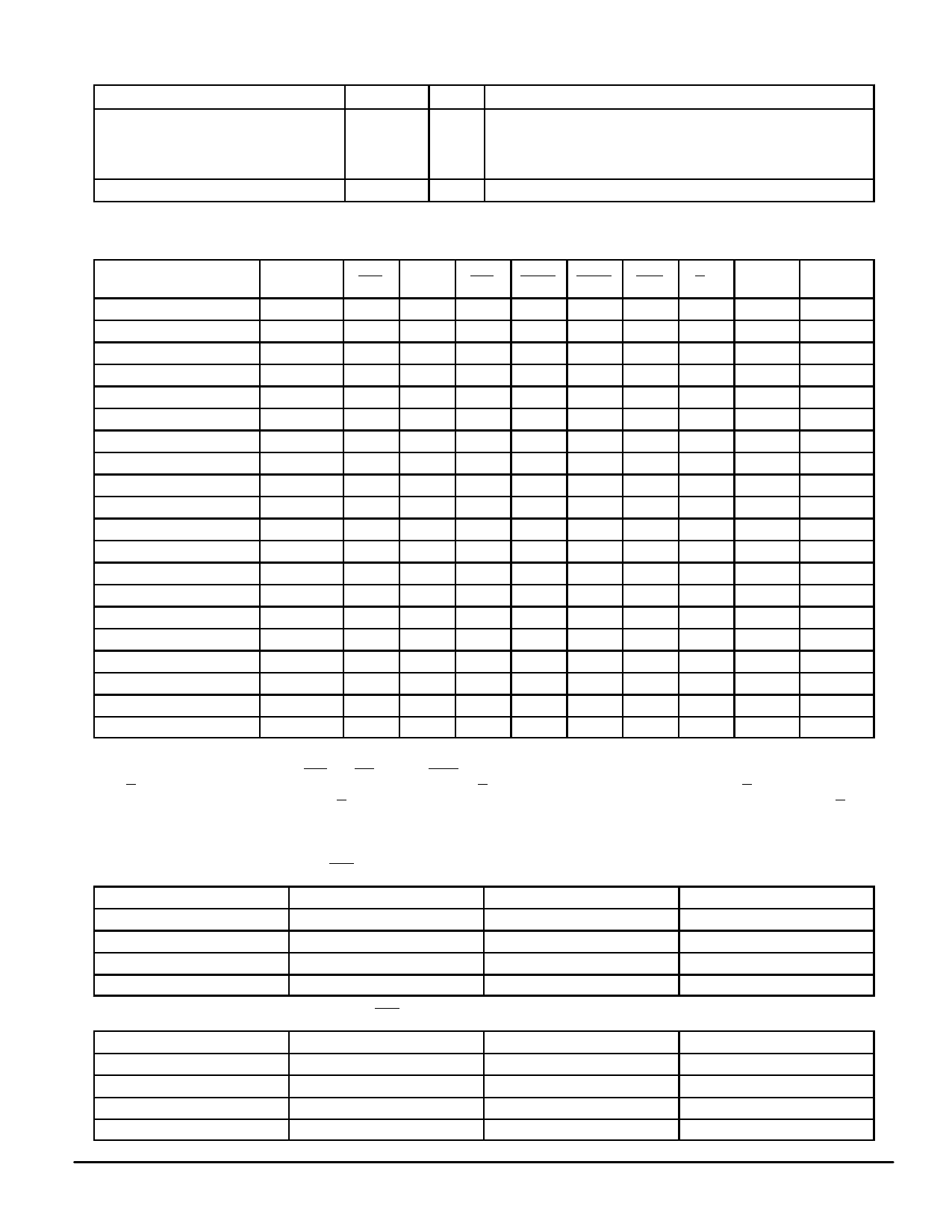
PIN DESCRIPTIONS (continued)
Pin Locations
D9, D11, E9, E11, F9, F11, G9 – G11,
H8 – H12, J8 – J12, K8 – K12, L8 – L12,
M8 – M12, N9 – N11, P9, P11, R9, R11,
T9, T11
K7, K13, P10, V7, V13, W7 – W13
Symbol
VSS
Type
Supply Ground.
Description
NC
— No Connection: There is no connection to the chip.
TRUTH TABLE (See Notes 1 through 5)
Next Cycle
Address
Used
SE1
SE2
SE3 ADSP ADSC ADV
G3
DQx Write 2, 4
Deselect
None
1
X
X
X
0
X
X
High–Z
X
Deselect
None
0
X
1
0
X
X
X
High–Z
X
Deselect
None
0
0
X
0
X
X
X
High–Z
X
Deselect
None
X
X
1
1
0
X
X
High–Z
X
Deselect
Begin Read
Begin Read
None
X
0
X
1
0
X
X
High–Z
X
External
0
1
0
0
X
X
X
High–Z
X5
External
0
1
0
1
0
X
X
High–Z READ5
Continue Read
Next
X
X
X
1
1
0
1
High–Z
READ
Continue Read
Next
X
X
X
1
1
0
0
DQ
READ
Continue Read
Next
1
X
X
X
1
0
1
High–Z
READ
Continue Read
Next
1
X
X
X
1
0
0
DQ
READ
Suspend Read
Current
X
X
X
1
1
1
1
High–Z
READ
Suspend Read
Current
X
X
X
1
1
1
0
DQ
READ
Suspend Read
Current
1
X
X
X
1
1
1
High–Z
READ
Suspend Read
Current
1
X
X
X
1
1
0
DQ
READ
Begin Write
External
0
1
0
1
0
X
X
High–Z WRITE
Continue Write
Next
X
X
X
1
1
0
X
High–Z WRITE
Continue Write
Next
1
X
X
X
1
0
X
High–Z WRITE
Suspend Write
Current
X
X
X
1
1
1
X
High–Z WRITE
Suspend Write
Current
1
X
X
X
1
1
X
High–Z WRITE
NOTES:
1. X = Don’t Care. 1 = logic high. 0 = logic low.
2. Write is defined as either 1) any SBx and SW low or 2) SGW is low.
3. G is an asynchronous signal and is not sampled by the clock K. G drives the bus immediately (tGLQX) following G going low.
4. On write cycles that follow read cycles, G must be negated prior to the start of the write cycle to ensure proper write data setup times. G must
also remain negated at the completion of the write cycle to ensure proper write data hold times.
5. This read assumes the RAM was previously deselected.
LINEAR BURST ADDRESS TABLE (LBO = VSS)
1st Address (External)
2nd Address (Internal)
X . . . X00
X . . . X01
X . . . X01
X . . . X10
X . . . X10
X . . . X11
X . . . X11
X . . . X00
3rd Address (Internal)
X . . . X10
X . . . X11
X . . . X00
X . . . X01
4th Address (Internal)
X . . . X11
X . . . X00
X . . . X01
X . . . X10
INTERLEAVED BURST ADDRESS TABLE (LBO = VDD)
1st Address (External)
2nd Address (Internal)
X . . . X00
X . . . X01
X . . . X01
X . . . X00
X . . . X10
X . . . X11
X . . . X11
X . . . X10
3rd Address (Internal)
X . . . X10
X . . . X11
X . . . X00
X . . . X01
4th Address (Internal)
X . . . X11
X . . . X10
X . . . X01
X . . . X00
MOTOROLA FAST SRAM
MCM72FB8ML MCM72PB8ML
5
Share Link: 