MAX9169ESE Просмотр технического описания (PDF) - Maxim Integrated
Номер в каталоге
Компоненты Описание
Список матч
MAX9169ESE Datasheet PDF : 19 Pages
| |||
4-Port LVDS and LVTTL-to-LVDS Repeaters
Detailed Description
LVDS is a signaling method for point-to-point and
multidrop data communication over a controlled-imped-
ance medium as defined by the ANSI TIA/EIA-644 and
IEEE 1596.3 standards. LVDS uses a lower voltage swing
than other common standards, achieving higher data
rates with reduced power consumption, while reducing
EMI emissions and system susceptibility to noise.
The MAX9169/MAX9170 are 630Mbps, four-port
repeaters for high-speed, low-power applications. The
MAX9169 accepts an LVDS input and has a fail-safe
input circuit. The MAX9170 features a +5V tolerant sin-
gle-ended LVTTL/LVCMOS input. Both devices repeat
the input at four LVDS outputs. The MAX9169 detects
differential signals as low as 50mV and as high as 1.2V
over a |VID|/2 to 2.4V - |VID|/2 common-mode range.
The MAX9170’s +5V tolerant LVTTL/LVCMOS input
includes circuitry to hold the decision threshold con-
stant at +1.5V over temperature and supply voltage.
The MAX9169/MAX9170 outputs use a current-steering
configuration to generate a 2.5mA to 4.5mA output cur-
rent. This current-steering approach induces less ground
bounce and shoot-through current, enhancing noise
margin and system speed performance. The outputs are
short-circuit current limited and are high impedance
when disabled or when the device is not powered.
The MAX9169/MAX9170 current-steering output requires
a resistive load to terminate the signal and complete the
transmission loop. Because the devices switch the direc-
tion of current flow and not voltage levels, the output volt-
age swing is determined by the value of the termination
resistor multiplied by the output current. With a typical
3.5mA output current, the MAX9169/MAX9170 produce
a 350mV output voltage when driving a transmission line
terminated with a 100Ω resistor (3.5mA ✕ 100Ω =
350mV). Logic states are determined by the direction of
current flow through the termination resistor.
Fail-Safe Circuitry
The fail-safe feature of the MAX9169 sets the outputs
high when the differential input is:
• Open
• Undriven and shorted
• Undriven and terminated
Without a fail-safe circuit, when the input is undriven,
noise at the input may switch the outputs and it may
appear to the system that data is being sent. Open or
undriven terminated input conditions can occur when a
cable is disconnected or cut, or when an LVDS driver
output is in high impedance. A shorted input can occur
because of cable failure.
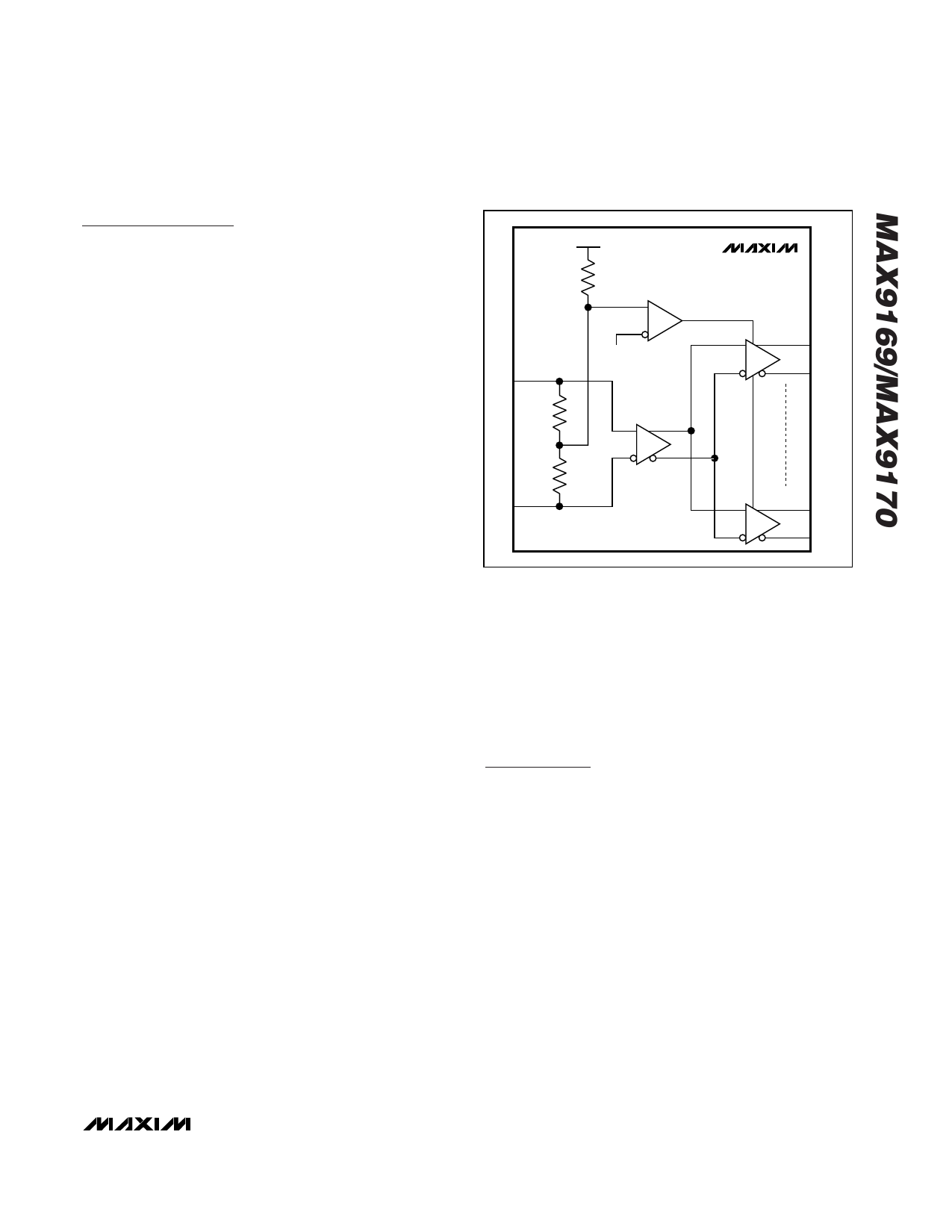
VCC
RIN2
MAX9169
COMPARATOR
IN+
RIN1/2
VCC - 0.3V
OUT1+
OUT1-
RIN1/2
IN-
RECEIVER
OUT4+
OUT4-
Figure 1. MAX9169 Input Fail-Safe Circuit
When the input is driven with signals meeting the LVDS
standard, the input common-mode voltage is less than
VCC - 0.3V and the fail-safe circuit is not activated
(Figure 1). If the input is open, undriven and shorted, or
undriven and parallel terminated, an internal resistor in
the fail-safe circuit pulls both the inputs above VCC -
0.3V, activating the fail-safe circuit and forcing the out-
puts high.
Applications Information
Supply Bypassing
Bypass VCC with high-frequency surface-mount ceram-
ic 0.1µF and 0.001µF capacitors in parallel as close to
the device as possible, with the smaller value capacitor
closest to the VCC pin. Use multiple parallel vias to min-
imize parasitic inductance.
Traces, Cables, and Connectors
The characteristics of differential input and output con-
nections affect the performance of the MAX9169/
MAX9170. Use controlled-impedance traces, cables,
and connectors with matched characteristic impedance.
Ensure that noise couples as common mode by run-
ning the traces of a differential pair close together.
Reduce within-pair skew by matching the electrical
length of the traces of a differential pair. Excessive
skew can result in a degradation of magnetic field can-
cellation. Maintain a constant distance between traces
of a differential pair to avoid discontinuities in differen-
_______________________________________________________________________________________ 7
Share Link: 