RF2905 Просмотр технического описания (PDF) - RF Micro Devices
Номер в каталоге
Компоненты Описание
Список матч
RF2905 Datasheet PDF : 22 Pages
| |||
RF2905
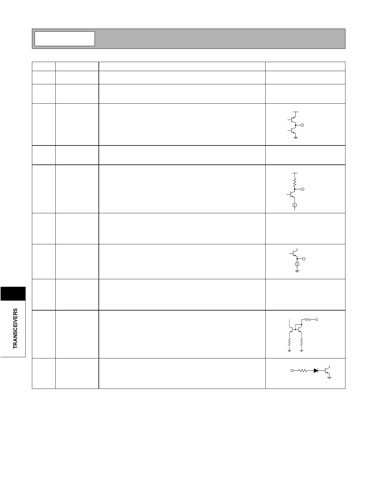
Pin Function Description
Interface Schematic
39
OSC E
This pin is connected directly to the emitter of the reference oscillator See pin 38.
transistors.
40
OSC B1 This pin is connected directly to the reference oscillator 1 transistor
See pin 38.
base. The intended reference oscillator configuration is a modified Col-
pitts.
41
LOOP FLT Output of the charge pump, and input to the VCO control. An RC net-
work from this pin to ground is used to establish the PLL bandwidth.
VCC
LOOP FLT
42
VREF P Bypass pin for the prescaler reference voltage. A 33nF capacitor to
ground is needed to suppress reference spurs in the device. This value
may be different for different PCB arrangements.
43 LOCK DET This pin provides an analog output indicating the lock status of the PLL.
The amplitude of this signal is typically 200mVPP around a DC level of
VCC-0.1 V.
VCC
20 kΩ
LOCK DET
44
VCC1
This pin is used to supply DC bias to the LNA, Mixer, first IF Amp, and
Bandgap reference. A RF bypass capacitor should be connected
directly to this pin and returned to ground. A 22pF capacitor is recom-
mended for 915MHz applications. A 68pF capacitor is recommended
for 433MHz applications.
45
PRESCL Dual-modulus/Dual-divide prescaler output. The output can be inter-
OUT
faced to an external PLL IC for additional flexibility in frequency pro-
gramming.
PRESCL
OUT
11
46
VCC3
This pin is used to supply DC bias and collector current to the transmit-
ter PA. A RF bypass capacitor should be connected directly to this pin
and returned to ground. A 22pF capacitor is recommended for 915MHz
applications. A 68pF capacitor is recommended for 433MHz applica-
tions.
47
LVL ADJ This pin is used to vary the transmitter output power. An output level
adjustment range greater than 12dB is provided through analog volt-
age control of this pin. DC current of the transmitter power amp ia also
reduced with output power. This pin MUST be low when the transmitter
is disabled.
40 kΩ
LVL ADJ
400 4 kΩ
48 PLL ENABL This pin is used to power up or down the VCO and PLL. A logic high
(PLLENABL>2.0V) powers up the VCO and PLL electronics. A logic
low (PLLENABL<1.0V) powers down the PLL and VCO.
PLL ENABL
50 kΩ
11-60
Rev B11 010516
Share Link: 