DS1077LU-40 Просмотр технического описания (PDF) - Dallas Semiconductor -> Maxim Integrated
Номер в каталоге
Компоненты Описание
Список матч
DS1077LU-40 Datasheet PDF : 20 Pages
| |||
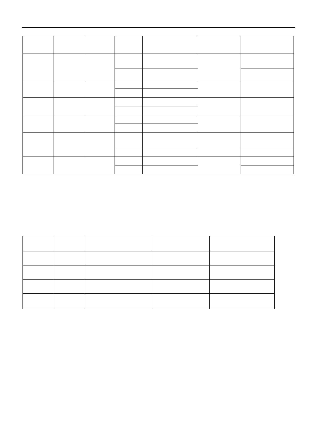
TABLE 1
DS1077L
EN0
(BIT)
0
SEL0
(BIT)
0
PDN0
(BIT)
0
CTRL0
(PIN)
1
0
OUT0
(PIN)
Hi-Z
(OUT1 and OUT2)
Hi-Z
CTRL0
FUNCTION
Power-Down*
DEVICE
MODE
Power-Down
Active
1
Master Clk/M
0
1
0
MUX Select
Active
0
Master Clk
1
Hi-Z
1
0
0
Output Enable
Active
0
Master Clk
1
Hi-Z
1
1
0
Output Enable
Active**
0
Master Clk/M
X
0
1
1
Hi-Z
(OUT1 and OUT2) Power-Down
Power-Down
0
Master Clk
Active
1
Hi-Z
Power-Down
X
1
1
Power-Down
0
Master Clk/M
Active
*This mode is for applications where OUT0 is not used, but CTRL0 is used as a device shutdown.
**Default Condition
CONTROL PIN 1 (CTRL1) – A multifunctional input pin that can be selected as an output enable
and/or a power-down. Its function is determined by the user-programmable control register value of
PDN1. (See Table 2.)
TABLE 2
PDN1 CTRL1
(BIT) (PIN)
0
0
CTRL1
FUNCTION
Output Enable
OUT 1
Out Clk
DEVICE MODE
Active*
0
1
Output Enable
Hi-Z
Active*
1
0
1
1
*Default Condition
Power-Down
Power-Down
Out Clk
Hi-Z
(OUT1 and OUT2)
Active
Power-Down
NOTE:
Both CTRL0 and CTRL1 can be configured as power-downs, they are internally “OR” connected so that
either of the control pins may be used to provide a power-down function for the whole device, subject to
appropriate settings of the PDN0 and PDN1 register bits. (See Table 3.)
4 of 20
Share Link: 