DS1073 Просмотр технического описания (PDF) - Dallas Semiconductor -> Maxim Integrated
Номер в каталоге
Компоненты Описание
Список матч
DS1073 Datasheet PDF : 18 Pages
| |||
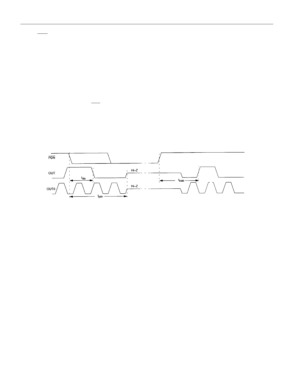
POWER-UP
When PDN is taken to a high level the following power-up sequence occurs:
1. Enable internal oscillator and/or OSCIN buffer.
2. Set M and N to maximum values.
3. Wait approximately 256 cycles of MCLK for it to stabilize.
4. Reset M and N to programmed values.
5. Enable OUT0 (assuming EN0 bit = 0).
6. Enable OUT.
Steps 2 through 4 exist to allow the oscillator to stabilize before enabling the outputs.
Figure 9
DS1073
POWER-ON RESET
When power is initially applied to the device supply pin, a power-on reset sequence is executed, similar
to that which occurs when the device is restored from a power-down condition. This sequence comprises
two stages, first a conventional POR to initialize all on-chip circuitry, followed by a stabilization period
to allow the oscillator to reach a stable frequency before enabling the outputs:
1. Initialize internal circuitry.
2. Enable internal oscillator and/or OSCIN buffer.
3. Set M and N to maximum values.
4. Wait approximately 256 cycles of MCLK for the oscillator to stabilize.
5. Load M and N programmed values from EEPROM.
6. Enable OUT0 (assuming EN0 = 0).
7. Enable OUT.
9 of 18
Share Link: 