RV5C338A-E2 Просмотр технического описания (PDF) - RICOH Co.,Ltd.
Номер в каталоге
Компоненты Описание
Список матч
RV5C338A-E2
RICOH Co.,Ltd.

RV5C338A-E2 Datasheet PDF : 52 Pages
| |||
R×5C338A
2) Level Mode : periodic interrupt signals are output with selectable interrupt cycle settings of 1 second, 1 minute, 1
hour, and 1 month. The increment of the second counter is synchronized with the falling edge of
periodic interrupt signals. For example, periodic interrupt signals with an interrupt cycle setting of
1 second are output in synchronization with the increment of the second counter as illustrated in
the timing chart below.
3) When the oscillation adjustment circuit is used, the interrupt cycle will fluctuate once per 20 seconds as follows:
Pulse Mode : the “L” period of output pulses will increment or decrement by a maximum of ±3.784ms.
For example, 1-Hz clock pulses will have a duty cycle of 50 ±0.3784%.
Level Mode : a periodic interrupt cycle of 1 second will increment or decrement by a maximum of ±3.784ms.
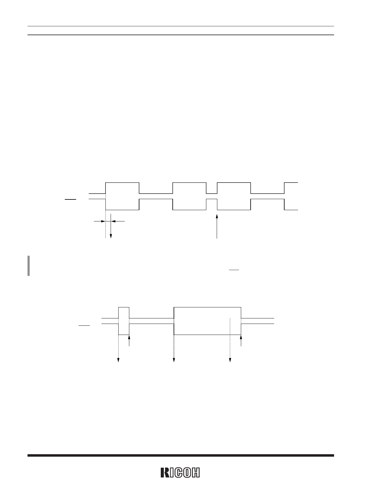
Relation Between the Mode Waveform and the CTFG Bit
• Pulse mode
CTFG bit
INTR pin
Approx. 92µs
(Increment of second counter)
Rewriting of the second counter
*) In the pulse mode, the increment of the second counter is delayed by approximately 92µs from the falling edge of clock pulses. Consequently, time
readings immediately after the falling edge of clock pulses may appear to lag behind the time counts of the real-time clocks by approximately 1 second.
Rewriting the second counter will reset the other time counters of less than 1 second, driving the INTR pin low.
• Level mode
CTFG bit
INTR pin
Setting CTFG bit to 0
(Increment of
second counter)
(Increment of
second counter)
Setting CTFG bit to 0
(Increment of
second counter)
12
Share Link: