RV5C338A-E2 Просмотр технического описания (PDF) - RICOH Co.,Ltd.
Номер в каталоге
Компоненты Описание
Список матч
RV5C338A-E2
RICOH Co.,Ltd.

RV5C338A-E2 Datasheet PDF : 52 Pages
| |||
R×5C338A
2.1-3 CLEN2
32-kHz Clock Output Bit 2
CLEN2
0
1
Description
Enabling the 32-kHz clock circuit
Disabling the 32-kHz clock circuit
(Default setting)
For the R×5C338A, setting the CLEN2 bit or the CLEN1 bit (D3 in the control register 2) to 0, and the CLKC pin to
high specifies generating clock pulses with the oscillation frequency of the 32.768-kHz crystal oscillator for output
from the 32KOUT pin. Conversely, setting both the CLEN1 and the CLEN2 bit to 1 or CLKC pin to low specifies
disabling (“L”) such output.
2.1-4 TEST
TEST
0
1
Test Bit
Normal operation mode
Test mode
Description
The TEST bit is used only for testing in the factory and should normally be set to 0.
(Default setting)
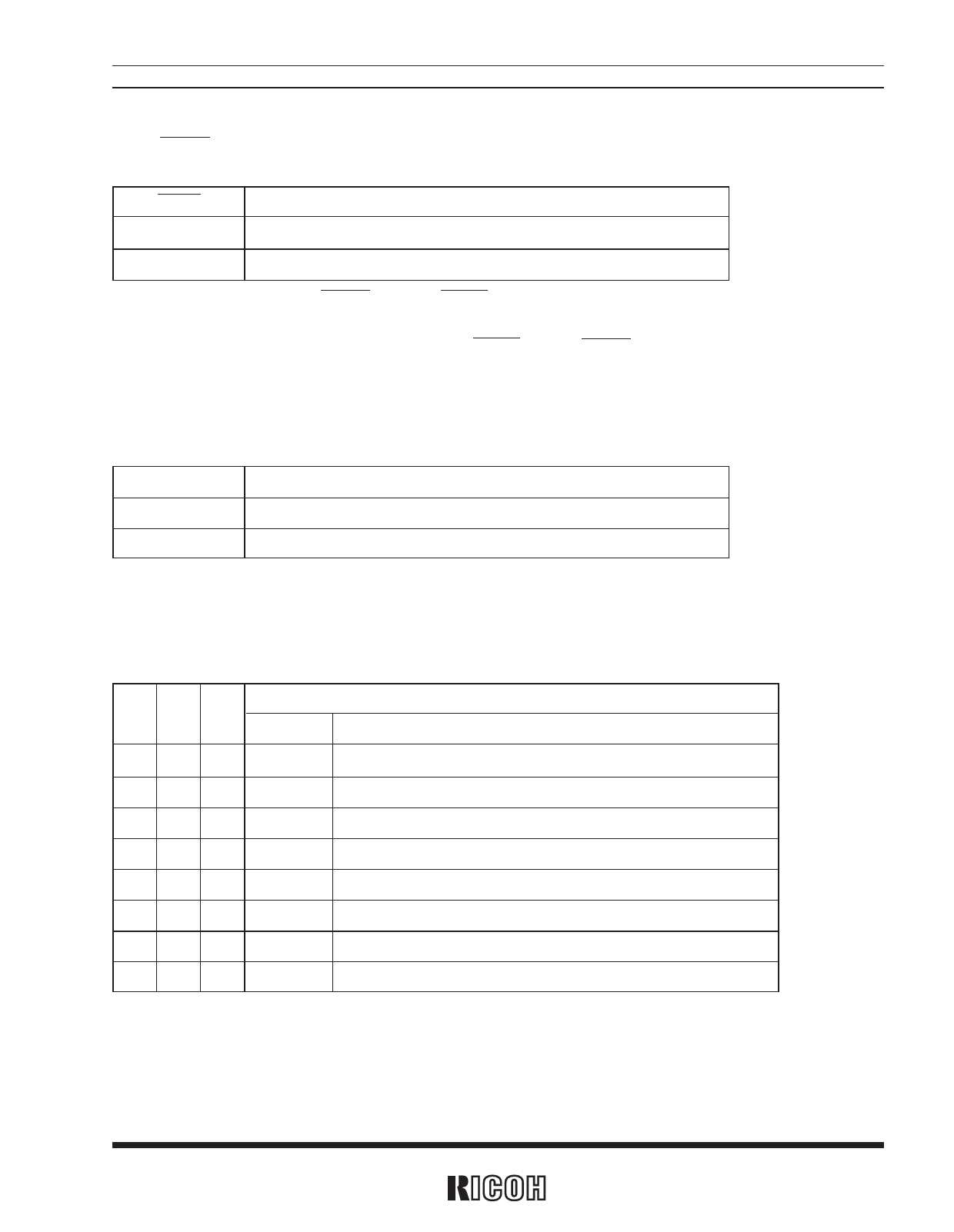
2.1-5 CT2, CT1, and CT0
Periodic Interrupt Selection Bits
CT2 CT1 CT0
Waveform mode
Description
Interrupt cycle and falling timing
0
0
0
—
Off (“H”)
(Default setting)
0
0
1
—
Fixed at low (“L”)
0
1
0 Pulse Mode 2Hz (Duty cycle of 50%)
0
1
1 Pulse Mode 1Hz (Duty cycle of 50%)
1
0
0 Level Mode Once per 1 second (Synchronized with second counter increment)
1
0
1 Level Mode Once per minute (at 00 seconds of every minute)
1
1
0 Level Mode Once per hour (at 00 minutes and 00 seconds of every hour)
1
1
1 Level Mode Once per month (at 00 hours, 00 minutes, and 00 seconds of first day of every month)
1) Pulse Mode : 2-Hz and 1-Hz clock pulses are output in synchronization with the increment of the second counter
as illustrated in the timing chart on the next page.
11
Share Link: