ADP130 Просмотр технического описания (PDF) - Analog Devices
Номер в каталоге
Компоненты Описание
Список матч
ADP130 Datasheet PDF : 20 Pages
| |||
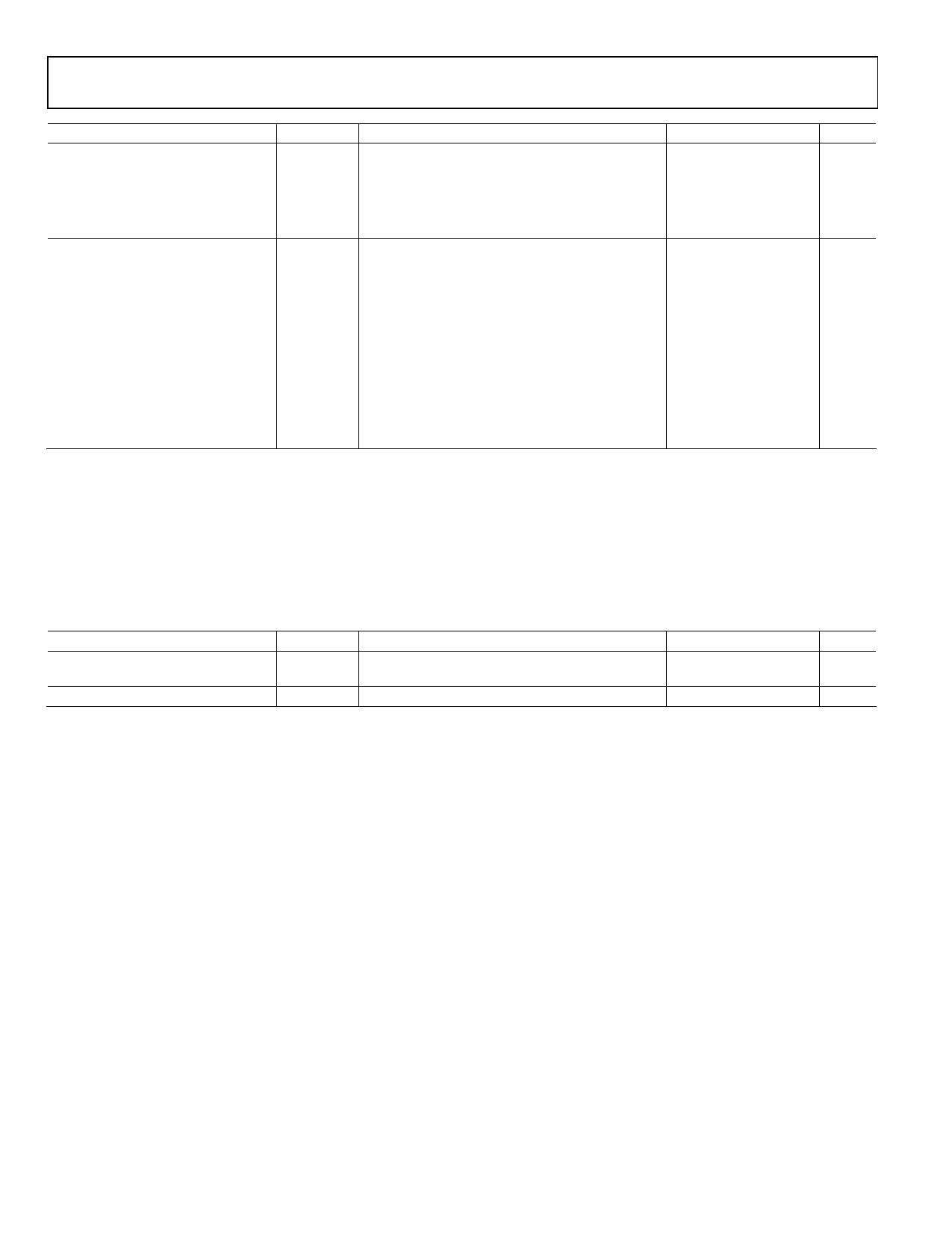
ADP130
Parameter
OUTPUT NOISE
POWER SUPPLY REJECTION RATIO
Symbol
OUTNOISE
PSRR
Conditions
Min Typ Max Unit
10 Hz to 100 kHz, VIN = 3.6 V, VOUT = 0.8 V
29
μV rms
10 Hz to 100 kHz, VIN = 3.6 V, VOUT = 1.2 V
38
μV rms
10 Hz to 100 kHz, VIN = 3.6 V, VOUT = 1.5 V
43
μV rms
10 Hz to 100 kHz, VIN = 3.6 V, VOUT = 2.5 V
61
μV rms
10 Hz to 100 kHz, VIN = 3.6 V, VOUT = 3.0 V
77
μV rms
Modulated bias, 10 kHz, VOUT = 3.0 V, VIN = 3.6 V,
VBIAS = 5 V
70
dB
Modulated bias, 100 kHz, VOUT = 3.0 V, VIN = 3.6 V,
53
dB
VBIAS = 5 V
Modulated VIN, 10 kHz, VOUT = 1.2 V, VIN = VOUT + 1 V,
70
dB
VBIAS = 5 V
Modulated VIN, 100 kHz, VOUT = 1.2 V, VIN = VOUT + 1 V,
54
dB
VBIAS = 5 V
Modulated VIN, 10 kHz, VOUT = 0.8 V, VIN = VOUT + 1 V,
70
dB
VBIAS = 5 V
Modulated VIN, 100 kHz, VOUT = 0.8 V, VIN = VOUT + 1 V,
55
dB
VBIAS = 5 V
1 IVIN = IGND − IBIAS, where IGND is the current flowing from the GND pin.
2 Based on an endpoint calculation using 1 mA and 350 mA loads.
3 Dropout voltage is defined as the input-to-output voltage differential when the input voltage is set to the nominal output voltage. This applies only for output
voltages above 1.3 V.
4 Start-up time is defined as the time from the rising edge of EN to VOUT being at 90% of its nominal value.
5 Current limit threshold is defined as the current at which the output voltage drops to 90% of the specified typical value. For example, the current limit for a 2.0 V
output voltage is defined as the current that causes the output voltage to drop to 90% of 2.0 V, or 1.8 V.
INPUT AND OUTPUT CAPACITOR, RECOMMENDED SPECIFICATIONS
Table 2.
Parameter
MINIMUM INPUT AND OUTPUT
CAPACITANCE1
CAPACITOR ESR
Symbol
CMIN
RESR
Conditions
TJ = −40°C to +125°C
TJ = −40°C to +125°C
Min Typ Max Unit
0.70 1
μF
.001
1
Ω
1 The minimum input and output capacitance should be >0.70 μF over the full range of operating conditions. The full range of operating conditions in the application
must be considered during device selection to ensure that the minimum capacitance specification is met. X7R and X5R type capacitors are recommended. Y5V and
Z5U capacitors are not recommended for use with any LDO.
Rev. 0 | Page 4 of 20
Share Link: 