ACT-F128K32 Просмотр технического описания (PDF) - Aeroflex Corporation
Номер в каталоге
Компоненты Описание
Список матч
ACT-F128K32 Datasheet PDF : 20 Pages
| |||
z
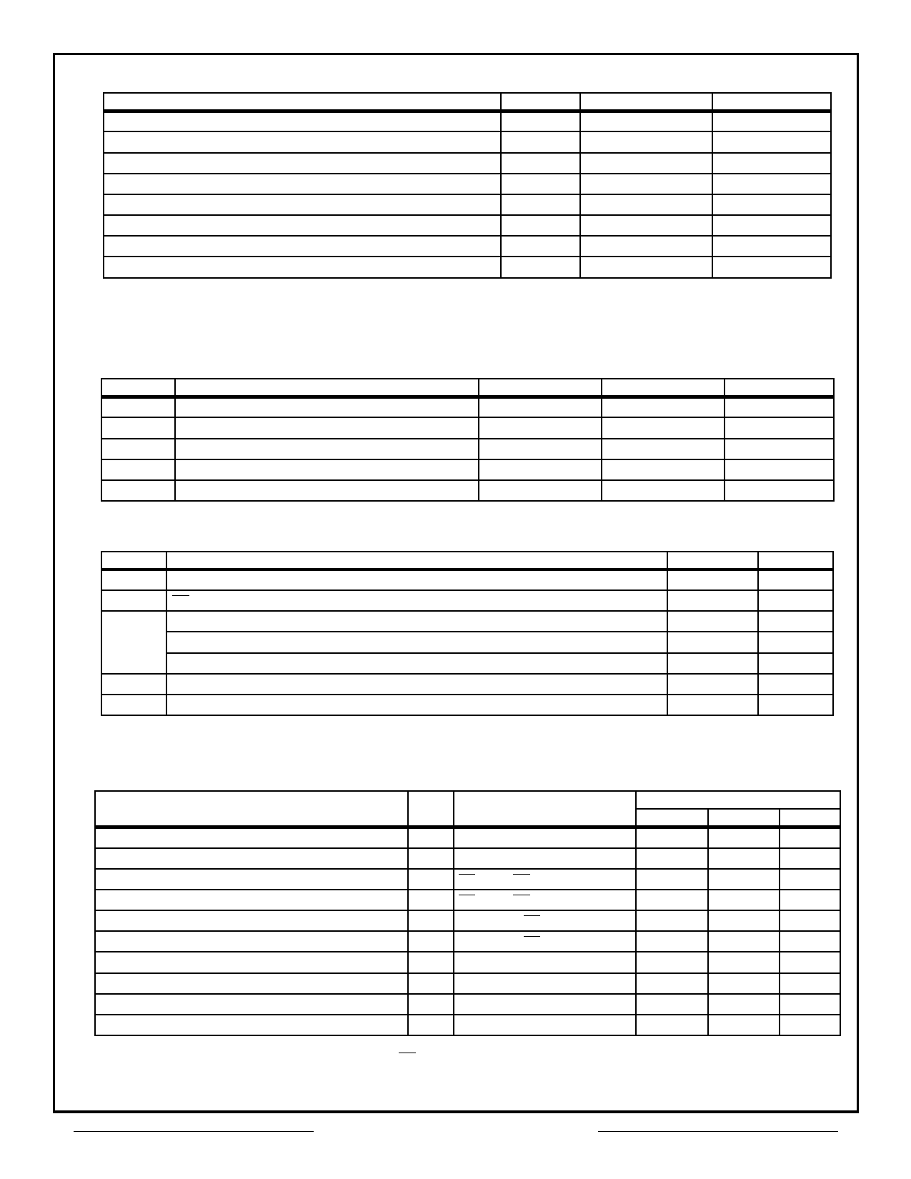
Absolute Maximum Ratings
Parameter
Case Operating Temperature
Storage Temperature Range
Supply Voltage Range
Signal Voltage Range (Any Pin Except A9) Note 1
Maximum Lead Temperature (10 seconds)
Data Retention
Endurance (Write/Erase cycles)
A9 Voltage for sector protect, Note 2
Symbol
TC
TSTG
VCC
VG
VID
Range
-55 to +125
-65 to +150
-2.0 to +7.0
-2.0 to +7.0
300
10
100,000 Minimum
-2.0 to +14.0
Units
°C
°C
V
V
°C
Years
V
Note 1. Minimum DC voltage on input or I/O pins is -0.5V. During voltage transitions, inputs may undershoot VSS to -2.0v for periods of up
to 20ns. Maximum DC voltage on input and I/O pins is VCC + 0.5V. During voltage transitions, inputs and I/O pins may overshoot to
VCC + 2.0V for periods up to 20 ns.
Note 2. Minimum DC input voltage on A9 is -0.5V. During voltage transitions, A9 may undershoot VSS to -2.0V for periods of up to 20ns.
Maximum DC input voltage on A9 is +12.5V which may overshoot to 14.0V for periods up to 20ns.
Symbol
VCC
VIH
VIL
TC
VID
Normal Operating Conditions
Parameter
Power Supply Voltage
Input High Voltage
Input Low Voltage
Operating Temperature (Military)
A9 Voltage for sector protect
Minimum
+4.5
+2.0
-0.5
-55
11.5
Maximum
+5.5
VCC + 0.5
+0.8
+125
12.5
Units
V
V
V
°C
V
Symbol Parameter
CAD
A0 – A16 Capacitance
COE
CWE
OE Capacitance
Write Enable Capacitance
CQFP(F5) Package
PGA(P3,P7) Package
CCE Chip Enable Capacitance
CI/O I/O0 – I/O31 Capacitance
Parameters Guaranteed but not tested
Capacitance
(VIN= 0V, f = 1MHz, TC = 25°C)
Maximum
50
50
20
20
20
20
Units
pF
pF
pF
pF
pF
pF
DC Characteristics – CMOS Compatible
(Vcc = 5.0V, Vss = 0V, TC = -55°C to +125°C, unless otherwise indicated)
Parameter
Sym
Conditions
Speeds 60, 70, 90, 120 & 150ns
Minimum Maximum Units
Input Leakage Current
ILI VCC = 5.5V, ViN = GND to VCC
10
µA
Output Leakage Current
Active Operating Supply Current for Read (1)
Active Operating Supply Current for Program or Erase(2)
ILOX32 VCC = 5.5V, ViN = GND to VCC
ICC1 CE = VIL, OE = VIH, f = 5MHz
ICC2 CE = VIL, OE = VIH
10
µA
140
mA
200
mA
Standby Supply Current
ICC3 VCC = 5.5V, CE = VIH, f = 5MHz
6.5
mA
Static Supply Current (4)
ICC4 VCC = 5.5V, CE = VIH
0.6
mA
Output Low Voltage
VOL IOL = +8.0 mA, VCC = 4.5V
0.45
V
Output High Voltage
VOH1 IOH = –2.5 mA, VCC = 4.5V
0.85 x VCC
V
Output High Voltage (4)
VOH2 IOH = –100 µA, VCC = 4.5V
VCC – 0.4
V
Low Power Supply Lock-Out Voltage (4)
VLKO
3.2
V
Note 1. The Icc current listed includes both the DC operating current and the frequency dependent component (At 5 MHz). The frequency
component typically is less than 2 mA/MHz, with OE at VIN.
Note 2. Icc active while Embedded Algorithm (Program or Erase) is in progress.
Note 3. DC Test conditions: VIL = 0.3V, VIH = VCC - 0.3V, unless otherwise indicated
Note 4. Parameter Guaranteed but not tested.
Aeroflex Circuit Technology
3
SCD1667 REV A 4/28/97 Plainview NY (516) 694-6700
Share Link: 