ZR36050 Просмотр технического описания (PDF) - Unspecified
Номер в каталоге
Компоненты Описание
Список матч
ZR36050 Datasheet PDF : 52 Pages
| |||
ADVANCE INFORMATION
ZR36050
Bits of MARKERS_EN are as follows:
APP. Reads the Application segment from the Internal Memory
and writes it to the compressed data during the Compression
Pass. Can also be used in a Tables-only Pass.
COM. Reads the Comment segment from the Internal Memory
and writes it to the compressed data during the Compression
Pass. Can also be used in a Tables-only Pass.
DRI. Enables the restart mechanism and writes the DRI marker
segment to the compressed data during the Compression Pass.
DQT. Reads the base Quantization Tables defined in the DQT
segment in the Internal Memory, multiplies the quantization
values by Scale Factor, rounds them to eight bits and writes the
results together with the DQT marker and parameters in the
compressed data during the Compression Pass or the Tables-
only Pass, and without the header in the internal quantization
tables during all passes. The number of Quantization Tables to
be processed is inferred from the LEN (segment length) param-
eter of the DQT segment.
DHT. Reads the DHT segment from the Internal Memory, and
writes it to the compressed data during the Compression Pass or
the Tables-only Pass.
DNL. Reads the DNL segment from the Internal memory and
writes it to the compressed file at the end of the first scan of Com-
pression Pass. In scans other than the first, the DNL bit is
ignored.
DQTI. Same function as the DQT bit, except the ZR36040 does
not transfer the DQT segment to the compressed data during the
Compression Pass. If DQT is set, then DQTI must be clear.
DHTI. Reads the Huffman Tables, defined in the DHT segment
of Internal Memory, and writes the decoded tables in the
Huffman Tables Store. The number of tables to decode and
store is inferred from the length parameter of the DHT segment.
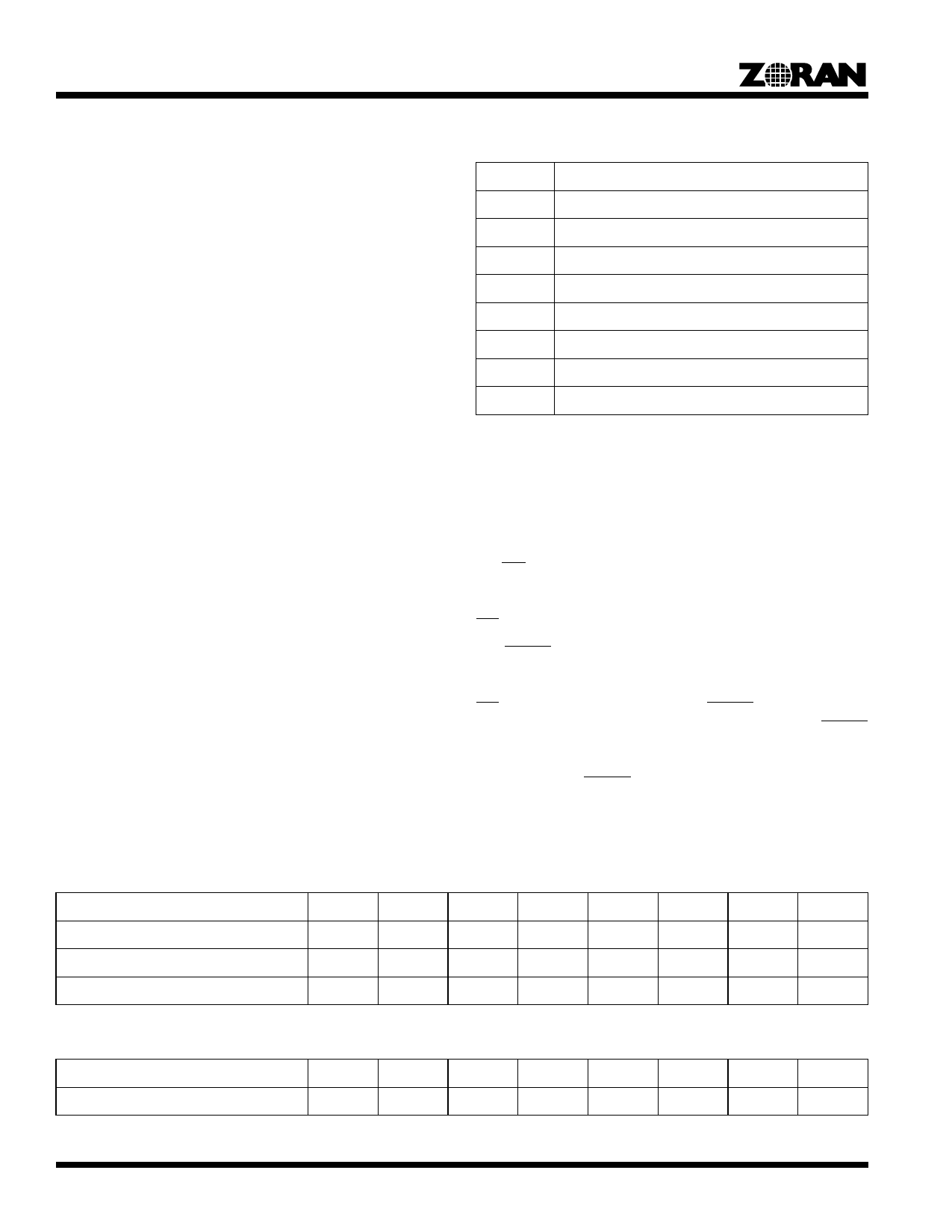
Table 6. NSCN Setting of the OPTIONS Register
NSCN
Number of Scans
000
1 scan
001
2 scans
010
3 scans
011
4 scans
100
5 scans
101
6 scans
110
7 scans
111
8 scans
INT_REQ_0, INT_REQ_1 and STATUS_0, STATUS_1
Registers
Two Interrupt Request registers are used in conjunction with two
corresponding STATUS registers, to enable generation of inter-
rupts to the host. If a bit in the Interrupt Request register is set,
the INT pin is activated when the corresponding bit in the
STATUS register becomes active, and the ZR36050 stops pro-
cessing and waits until the host restarts it with a GO command.
INT is deactivated when the host reads the STATUS register.
The RESET pulse, GO command, or reading the STATUS reg-
isters reset the bits in the STATUS_(0,1), (except for the END
and DATRDY bits of the STATUS_1 register), and disable the
INT signal. The END bit is set by the RESET pulse and is reset
by the GO command. The DATRDY bit gets reset by a RESET
pulse but is unaffected by the GO command (see DATRDY
description). Table 9 summarizes the effects of reading the
STATUS_1 bits, RESET pulse, and the GO command on the
STATUS_1 register.
Table 7. Programming the ZR36050 for Decoding Modes
Decoding Mode
COMP
ATP
PASS2
TLM
DC Only
BRC
NSCN
OVF
JPEG Baseline Expansion Pass
0
0
0
0
0
0
0
0
Fast Preview
0
0
0
0
1
0
0
0
Tables Preload for Decoding
0
0
0
1
0
0
0
0
Table 8. Programming the ZR36050 for JPEG Lossless Decoding Mode
JPEG Lossless Decoding Mode
COMP
ATP
PASS2
TLM
DC Only
BRC
NSCN
OVF
JPEG Lossless Expansion Pass
0
0
0
0
0
0
0
0
30
Share Link: 