CDP1020 Просмотр технического описания (PDF) - Intersil
Номер в каталоге
Компоненты Описание
Список матч
CDP1020 Datasheet PDF : 23 Pages
| |||
CDP1020
Hardware Interface
The hardware interface of the CDP1020 is designed to be fully
compliant with the Device Bay specification 0.90 and includes
many optional and value-added features that reduce system
component count, system complexity and overall system cost.
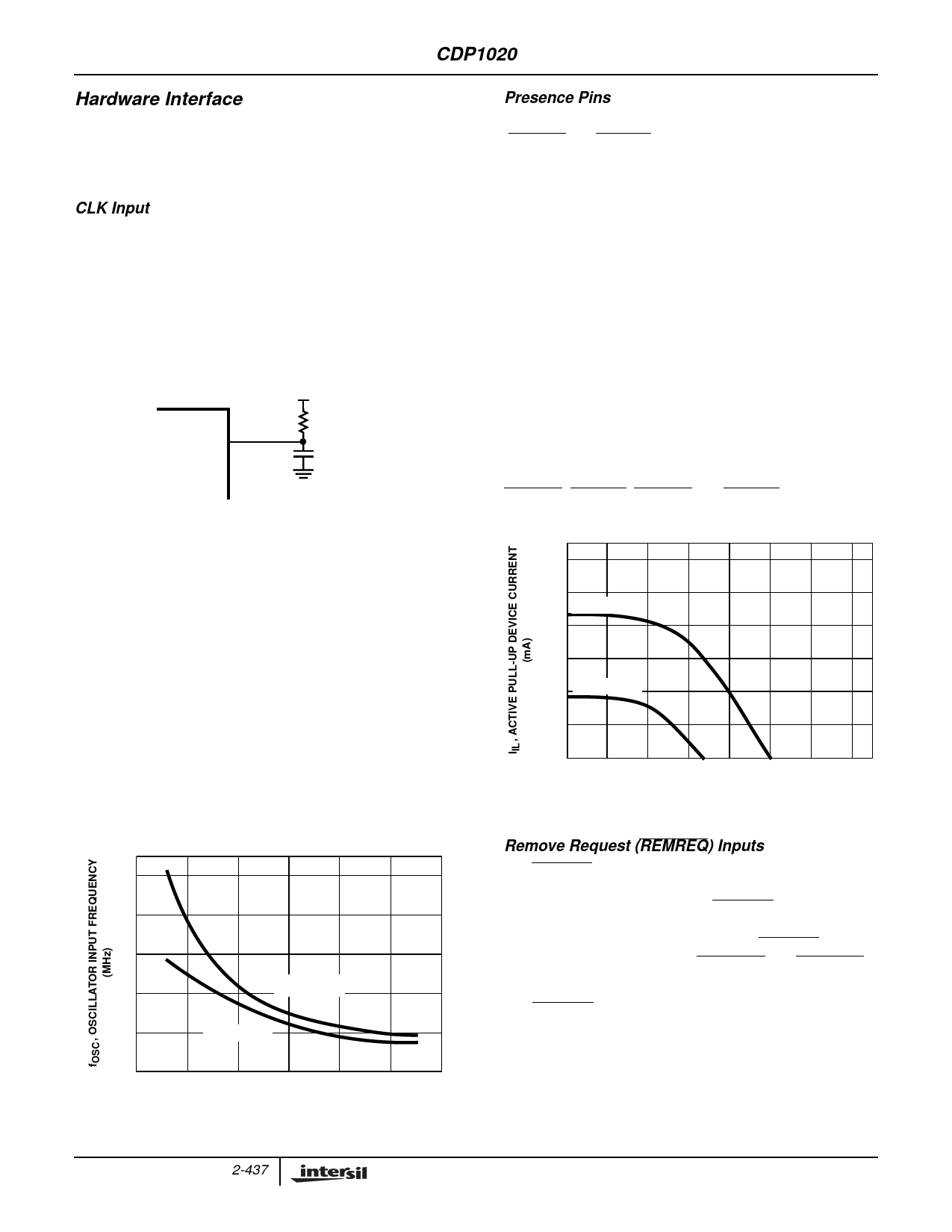
CLK Input
As stated at the beginning of this document, the Clock input
(CLK) provides the basic time base reference for operation of
all CDP1020 control logic (SMBus transfers between the
CDP1020 and the SMBus Host controller are not based on the
clock input). The clock input of the CDP1020 has the circuitry
necessary for oscillating an external resistor-capacitor circuit,
as shown in Figure 10. External clock sources (like those from
a can oscillator) should not be used with the CDP1020.
VDD = 5.0V
CLK 26
CDP1020
4.7kΩ
100pF
FIGURE 10. RC OSCILLATOR CONFIGURATION
The input frequency of the CDP1020 will vary for different
values of the oscillator resistor, the oscillator capacitor and
VDD. The CDP1020 is designed to operate optimally with an
input frequency of 4MHz. All of the internal timing of the
CDP1020, including debounce, insertion delay, and solenoid
pulse durations are based on a 4MHz input. While the
CDP1020 will operate at any frequency in the 3.0MHz to
5.0MHz range, an input frequency of 4MHz is strongly
recommended. Also, it is recommended that the value of the
oscillator capacitor be fixed at 100pF for optimal operation of
the oscillator.
Figure 11 shows a plot of oscillator frequency vs. resistance
at 5.0V and 3.3V when the oscillator capacitance is held
fixed at 100pF. Recommended values for the oscillator when
VDD = 5.0V are 4.7kΩ and 100pF; 3.3kΩ and 100pF when
VDD = 3.3V.
10
8
6
4
VDD = 5.0V
2
VDD = 3.3V
0
2.0
4.0
6.0
8.0
10.0
ROSC, OSCILLATOR RESISTOR (kΩ)
FIGURE 11. OSCILLATOR FREQUENCY vs ROSC (COSC = 100pF)
Presence Pins
The CDP1020 has two device presence detect inputs
(1394PRx and USBPRx) for each bay, for a total of four in all.
These inputs are mandatory in the Device Bay specification
and are the primary means of notifying the system that a
device has been inserted into a bay. Figure 18 shows a
typical connection of the CDP1020 presence pins.
The 1394 and USB presence lines are pulled up to the VDD of
the CDP1020 through active pull-up resistors located on the
CDP1020. These on chip resistors eliminate the need for
external pull-ups. Whenever any device is inserted into a bay,
that device must pull at least one (and possibly both) of the
presence pins to ground. Doing so indicates to the CDP1020
that a new device has been inserted and what communications
protocol it uses. Also, all presence pin inputs to the CDP1020
are debounced internally. The debounce time is set internally to
approximately 1 second to allow for transitions in the presence
pin state while the device is being inserted.
Typical current vs. voltage curves for the presence pin pull-
up resistor are shown in Figure 12. Pin assignments for
1394PR0, USBPR0, 1394PR1 and USBPR1 are shown on
the cover page and in Figure 2.
300
250
VDD = 5.0V
200
150
100 VDD = 3.3V
50
0
1.0 2.0 3.0 4.0 5.0 6.0
VI, INPUT VOLTAGE (V)
FIGURE 12. TYPICAL ACTIVE PULL-UP CURRENT AT 25oC
Remove Request (REMREQ) Inputs
The REMREQ inputs connect to an external, panel mounted
push button that allows the user to request removal of a
device. The implementation of the REMREQ feature is an
optional but encouraged feature of Device Bay specification
0.90. Each bay is assigned its own unique REMREQ input, as
such the CDP1020 implements REMREQ0 and REMREQ1.
Typical connection to a push button is shown in Figure 18.
The REMREQ inputs, like the presence pins, incorporate
integrated internal active pull-up devices. This allows the
system designer to implement the push button as a simple
momentary-on switch that pulls the input to ground when
pressed. When pressed, the CDP1020 will debounce the
switch press internally. No external pull-up resistors or
lowpass debounce filters are necessary.
2-437
Share Link: 