SPX1117T-L Просмотр технического описания (PDF) - Exar Corporation
Номер в каталоге
Компоненты Описание
Список матч
SPX1117T-L Datasheet PDF : 11 Pages
| |||
SPX1117
800mA Low Dropout Voltage Regulator
layer on the backside of the substrate. Refer
to table 1 for the results of the experiment.
The thermal interaction from other
components in the application can affect the
thermal resistance of the SPX1117. The actual
thermal resistance can be determined with
experimentation.
SPX1117 power dissipation is calculated as
follows:
Maximum Junction Temperature
.
Maximum junction temperature must not
exceed 125°C.
Where
C: value of capacitor in Farads
FR: ripple frequency in Hz
R1: value of resistor R1 in ohms
If an ADJ-bypass capacitor is used, the
amplitude of the output ripple will be
independent of the output voltage. If an ADJ-
bypass capacitor is not used, the output ripple
will be proportional to the ratio of the output
voltage to the reference voltage:
Where M=multiplier for the ripple seen when
the ADJ pin is optimally bypassed.
VREF=1.25V
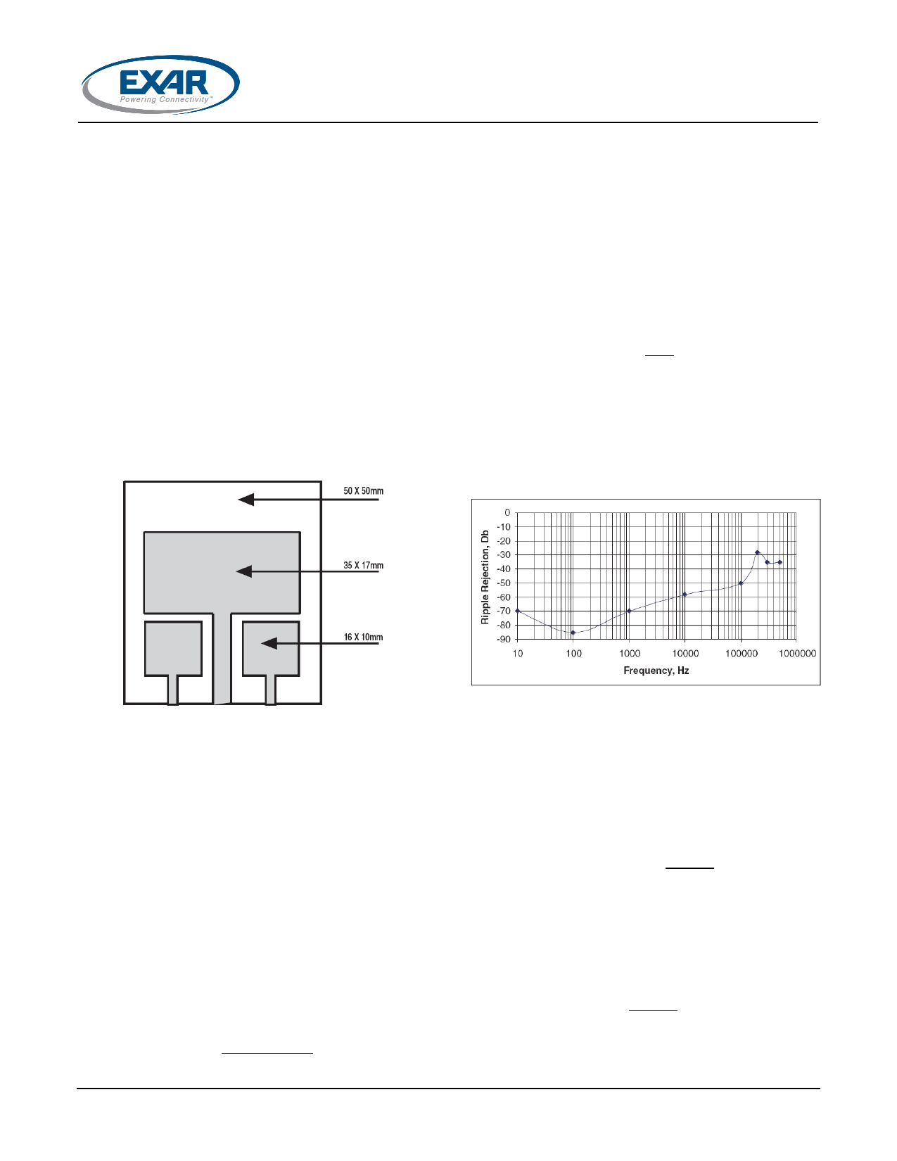
Ripple rejection for the adjustable version is
shown in Figure 20.
Fig. 19: Substrate Layout for SOT-223
RIPPLE REJECTION
Ripple rejection can be improved by adding a
capacitor between the ADJ pin and ground as
shown in Figure 23. When ADJ pin bypassing
is used, the value of the output capacitor
required increases to its maximum. If the ADJ
pin is not bypassed, the value of the output
capacitor can be lowered to 10μF for an
electrolytic aluminum capacitor or 2.2μF for a
ceramic or solid tantalum capacitor (Fig 22).
However the value of the ADJ-bypass
capacitor should be chosen with respect to the
following equation:
Fig. 20: Ripple Rejection
VIN=3.3V, VOUT=1.8V(adj), ILOAD=200mA
OUTPUT VOLTAGE
The output of the adjustable regulator can be
set to any voltage between 1.25V and 15V.
The value of VOUT can be quickly approximated
using the formula
1.25
A small correction to this formula is required
depending on the values of resistors R1 and
R2, since the adjustable pin current (approx
50μA) flows through R2. When IADJ is taken
into account, the formula becomes
1
6.28
© 2011 Exar Corporation
Where VREF=1.25V
7/11
Rev. 2.1.0
Share Link: 