SPX1117T-L Просмотр технического описания (PDF) - Exar Corporation
Номер в каталоге
Компоненты Описание
Список матч
SPX1117T-L Datasheet PDF : 11 Pages
| |||
SPX1117
800mA Low Dropout Voltage Regulator
APPLICATION INFORMATION
OUTPUT CAPACITOR
To ensure the stability of the SPX1117, an
output capacitor of at least 2.2µF (tantalum or
ceramic) or 10µF (aluminum) is required. The
value may change based on the application
requirements of the output load or
temperature range. The value of ESR can vary
based on the type of capacitor used in the
applications to guarantee stability. The
recommended value for ESR is 0.5Ωor less. A
larger value of output capacitance (up to
100µF) can improve the load transient
response.
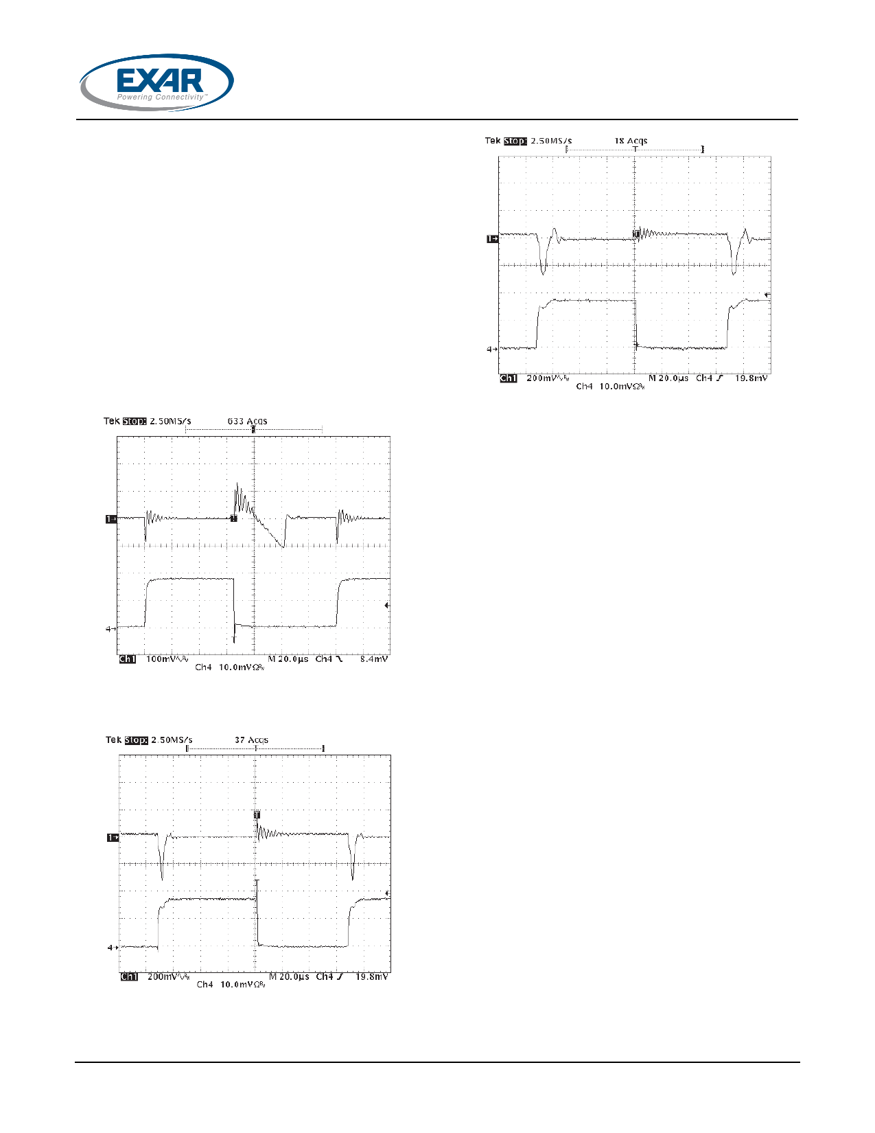
Fig. 18
Fig. 16: Load Step Response 0mA to 800mA
VIN=3.3V, VOUT=1.8V, CIN=10µF, COUT=2.2µF, Ceramic
Signal 1=VOUT, Signal 4=ILOAD
SOLDERING METHODS
The SPX1117 SOT-223 package is designed to
be compatible with infrared reflow or vapor-
phase reflow soldering techniques. During
soldering, the non-active or mildly active
fluxes may be used. The SPX1117 die is
attached to the heatsink lead which exits
opposite the input, output, and ground pins.
Hand soldering and wave soldering should be
avoided since these methods can cause
damage to the device with excessive thermal
gradients on the package. The SOT-223
recommended soldering method are as
follows: vapor phase reflow and infrared
reflow with the component preheated to within
65C of the soldering temperature range.
Fig. 17: Load Step Response 0mA to 800mA
VIN=3.3V, VOUT=1.8V, CIN=10µF, COUT=2.2µF, OSCON
Signal 1=VOUT, Signal 4=ILOAD
© 2011 Exar Corporation
THERMAL CHARACTERISTICS
The thermal resistance of SPX1117 (SOT-223
package) is 15°C/W from junction to tab and
31°C/W from tab to ambient for a total of 46
°C/W from junction to ambient (Table 1). The
SPX1117 features the internal thermal limiting
to protect the device during overload
conditions. Special care needs to be taken
during continuous load conditions such that
the maximum junction temperature does not
exceed 125 °C. Thermal protection is activated
at >155°C and deactivated at <140 °C.
Taking the FR-4 printed circuit board and 1/16
thick with 1 ounce copper foil as an
experiment (fig.19), the PCB material is
effective at transmitting heat with the tab
attached to the pad area and a ground plane
6/11
Rev. 2.1.0
Share Link: 