MAX8704 Просмотр технического описания (PDF) - Maxim Integrated
Номер в каталоге
Компоненты Описание
Список матч
MAX8704
Maxim Integrated

MAX8704 Datasheet PDF : 13 Pages
| |||
High-Current, Low-Voltage Linear Regulator
with Power-Limited, External MOSFET
load current. Bypass VCC with a 1µF or greater ceramic
capacitor as close to the MAX8704 as possible.
Undervoltage Lockout (UVLO)
The VCC input undervoltage-lockout (UVLO) circuitry
ensures that the regulator starts up with a gate-drive
voltage that can adequately bias the external n-channel
MOSFET. The UVLO threshold is 4.2V (typ), and VCC
must remain above this level for proper operation.
Power-Supply Input (VIN)
The power input supply (VIN) sources the current
required by the linear regulator’s output (VOUT). VIN
connects to the drain of the external n-channel power
MOSFET. VIN may be as low as 1.0V, minimizing the
power dissipation across the n-channel MOSFET.
Bypass VIN with a 10µF or greater capacitor as close to
the external MOSFET as possible. To avoid input volt-
age sag during a load transient, the input supply
should provide a low source impedance. If a high-
impedance source is used, additional input bulk
capacitance is required near the MAX8704.
Soft-Start and Enable (SS/EN)
As shown in Figure 2, a capacitor on SS/EN allows a
gradual buildup of the MAX8704 current limit, reducing
the initial inrush current peaks at startup. The input sup-
ply UVLO and thermal-overload fault trigger the internal
SS/EN pulldown resistor (RSS/EN = 1kΩ), automatically
forcing the MAX8704 into shutdown. When properly
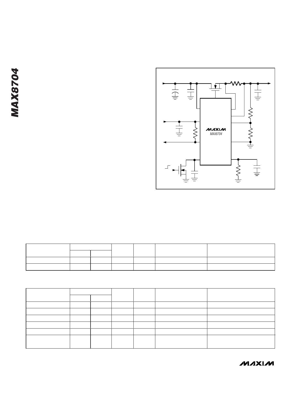
INPUT
1.8V TO 5.5V
CIN1
100µF
CIN2
10µF
5V BIAS
SUPPLY
C1
1.0µF
R3
100kΩ
POWER-
GOOD
OFF
ON
N1
IRF7401
RSENSE
10mΩ
DRV
VIN
CSP
CSN
VCC
FB
MAX8704
PGOOD
GND
OUTPUT (VOUT)
1.5V AT 5A (MAX)
COUT
2 x 22µF
R1
20kΩ
R2
10kΩ
SS/EN
CSS
0.01µF
PLIM
RPLIM
200kΩ
CPLIM
0.1µF
Figure 1. Standard Application Circuit
powered (VCC above UVLO), the MAX8704 charges the
soft-start capacitor with a constant 5µA current source
(see the Soft-Start Capacitor Selection section). Once
the SS/EN voltage rises above 0.5V, the linear regulator
Table 1. MOSFET Selection (>1.5V Output-Voltage Applications)
MOSFET
RDS(ON) (mΩ)
VDS
CISS*
2.5V
1.8V
(V)
(nF)
PACKAGE
VENDOR
FDS6574A
7
9
20
8
SO-8 (2.5W)
Fairchild
Si4836DY
4
5
12
7
SO-8 (2.5W)
Siliconix (Vishay)
*CISS when VDS = 1V
Table 2. MOSFET Selection (0.5V to 1.5V Output-Voltage Applications)
MOSFET
IRF7401
NDS8425
FDS6572A
FDS7064N
Si9426DY
Si4866DY
Si7882DP
RDS(ON) (mΩ)
VDS
CISS*
4.5V
2.5V
(V)
(nF)
22
30
20
2.7
PACKAGE
SO-8 (2.5W)
22
28
20
1.4
SO-8 (2.5W)
6
8
20
6.2
SO-8 (2.5W)
7.5
—
30
3.7
Bottomless SO-8 (3W)
13.5
16
20
3.5
SO-8 (2.5W)
5.5
8
12
3.2
SO-8 (2.5W)
PowerPAK (5W)
VENDOR
International Rectifier
Fairchild
Fairchild
Fairchild
Siliconix (Vishay)
Siliconix (Vishay)
*CISS when VDS = 1V
8 _______________________________________________________________________________________
Share Link: