M74HCT646 Просмотр технического описания (PDF) - STMicroelectronics
Номер в каталоге
Компоненты Описание
Список матч
M74HCT646 Datasheet PDF : 15 Pages
| |||
M74HCT646
OCTAL BUS TRANSCEIVER/REGISTER
WITH 3 STATE OUTPUTS
s HIGH SPEED:
fMAX = 60 MHz (TYP.) at VCC = 4.5V
s LOW POWER DISSIPATION:
ICC = 4µA(MAX.) at TA=25°C
s COMPATIBLE WITH TTL OUTPUTS :
VIH = 2V (MIN.) VIL = 0.8V (MAX)
s SYMMETRICAL OUTPUT IMPEDANCE:
|IOH| = IOL = 6mA (MIN)
s BALANCED PROPAGATION DELAYS:
tPLH ≅ tPHL
s PIN AND FUNCTION COMPATIBLE WITH
74 SERIES 646
DESCRIPTION
The 74HCT646 is an advanced high-speed
CMOS OCTAL BUS TRANSCEIVER AND
REGISTER (3-STATE) fabricated with silicon gate
C2MOS technology.
This device consists of bus transceiver circuits
with 3 state, D-type flip-flops, and control circuitry
arranged for multiplexed transmission of data
directly from the input bus or from the internal
registers. Data on the A or B bus will be clocked
into register on the low to high transition of the
appropriate clock pin (Clock AB or Clock BA).
Enable (G) and direction (DIR) pins are provided
to control the transceiver functions. In the
transceiver mode, data present at the
high-impedance port may be stored in either
register or in both. The select controls (Select AB
DIP
SOP
TSSOP
ORDER CODES
PACKAGE
TUBE
T&R
DIP
SOP
TSSOP
M74HCT646B1R
M74HCT646M1R M74HCT646RM13TR
M74HCT646TTR
select BA) can multiplex stored and real time
(transparent mode) data. The direction control
determines which bus will receive data when
enable G is active (low). In the isolation mode
(enable G high), "A" data may be stored in one
register and/or "B" data may be stored in the other
register. When an output function is disabled, the
input function is still enabled and may be used to
store and transmit data. Only one of the two
buses, A or B, may be driven at a time.
All inputs are equipped with protection circuits
against static discharge and transient excess
voltage.
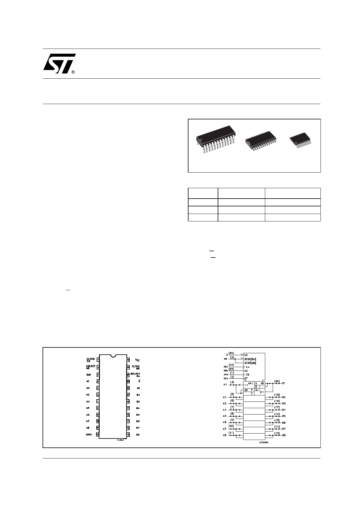
PIN CONNECTION AND IEC LOGIC SYMBOLS
April 2003
1/15
Share Link: 